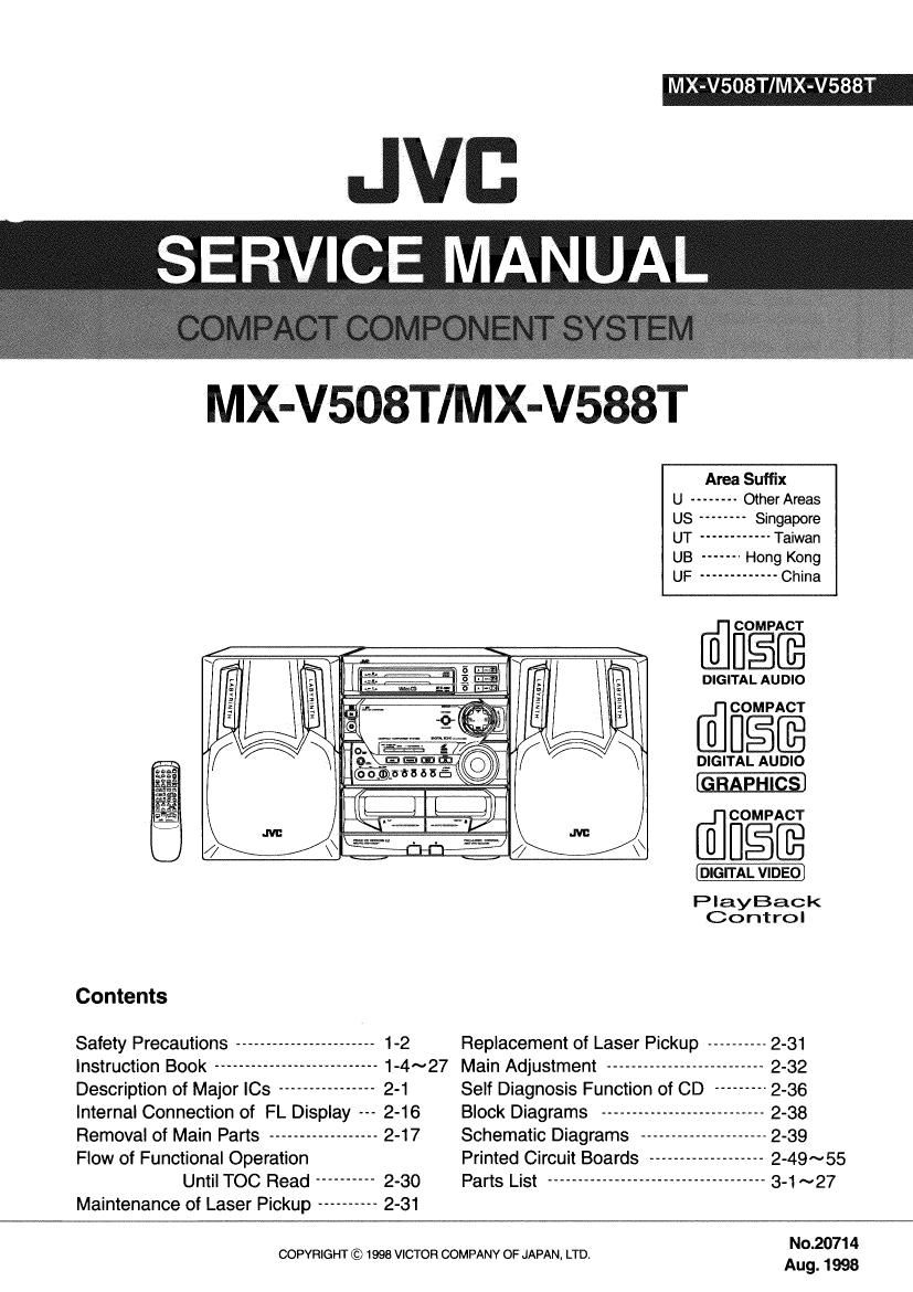
Jvc MXV 588 T Service Manual

This is the 40 pages manual for Jvc MXV 588 T Service Manual.
Read or download the pdf for free. If you want to contribute, please mail your pdfs to info@audioservicemanuals.com.

Page: 1 / 40
left right
Jvc MXV 588 T Service Manual

Extracted text from Jvc MXV 588 T Service Manual (Ocr-read)


Page 1

MX-V508T/MX-V588T

JVB
SERVICEMANUAL ;

M-508X-5VT/MV8T

Area Suffix
U -------- Other Areas
US -------- Singapore
UT ------------ Taiwan
UB ------- Hong Kong
UF ------------- China

fiilfiifi

DIGITAL AUDIO
_r COMPACT

U BEE

DIGITAL AUDIO

COMPACT
\\ @3593

PlayBack
Control

Contents

Safety Precautions ----------------------- 1-2 Replacement of Laser Pickup ---------- 2-31
Instruction Book --------------------------- 1-4~27 Main Adjustment -------------------------- 2-32
Description of Major ICs ---------------- 2-1 Self Diagnosis Function of CD --------- 2-36
Internal Connection of FL Display 2-16 Block Diagrams --------------------------- 2-38
Removal of Main Parts ------------------ 2-17 Schematic Diagrams --------------------- 2-39
Flow of Functional Operation Printed Circuit Boards ------------------- 2-49~55
Until TOC Read ---------- 2-30 Parts List ------------------------------------ 3-1 ~27

Maintenance of Laser Pickup ---------- 2-31

No.2071 4

COPYRIGHT © 1998 VICTOR COMPANY OF JAPAN, LTDt
Aug. 1998

Page 2

MX-V508T/MX-V588T

Description of Major ICs
I UP078044FGF-089(IC701):System Control Micon

1.Trmina| Layout

80 ~ 65
64
2
41
25 ~ 40
2.Pin Function
Pin No. Symbol I/O Function Pin No. Symbol |/o Function
1~7 7G~1G 0 FL Grid control signal 39 m 0 5V switch
8 VDD - Power supply +5V 4o MRESET 0 Reset signal output.
9 SCKO 0 Serial Clock (PLL,SLC.VoI,C3) 41 oscx 0 Clock signal to I0106
10 SDATAO 0 Serial data (PLL.SLC,Vo|,CS) 42 0808 0 Chip select signal to lCt 06
11 W 0 AUX Indicator contrOI 43 oso o Micon command data to |0251
12 m 0 TAPE Indicator control 44 DSPSTB O Strobe changer control
13 SLC-STTA 0 Strobe Tape control 45 OSDATA 0 05 Data to IC106
14 MCLK 0 Sub code clock
15 MCMND 0 CD Mocha command data 46 POUT 0 Power onlofl
16 MSTAT l Sub code data 47 REM | Remote control
17 W | System reset signal 48 ICVss - To ground
13 PHOTO A | Tape A mechanism running detection 49 m 0 System mute
19 PHOTO B | Tape 8 mechanism running detection 50 MRDY 0 Ready signal to ICZSi
20 AVss - AD Ground 51 F.TU 0 Function TUNER
21 NC | TEST (Normally 'H") 52 Vdd - Power supply +5V
22 SAFETY1 I Trouble detection 53 VOL- l Volume encorder input (-)
23 SLC KEYS ' Tape A playback detect WHO 54 VOL+ l Volume enoorder input (+)
24 SLC KEY2 l Tape 3 playback detect SWilCh 55 SPK 0 Speaker relay control signal
25 SLC KEY1 | Tape B playbacldREC detect switch 56 PROTECTOR l Protector input
26~28 KEY3~1 | Key matrix input 57 BACKUP | Backup detect
29 AVdd - AD+5V 58 LATCH O Latch signal to K3302
30 AVREF - AD REF + 5V 59 PEliOD 0 Tuner PLL strobe
31 XT1 | Sub clock 32.768kHz 60~70 $1~S11 0 FL segment control signal
32 XT2 0 Sub clock 32.788kHz 71 VLOAD - Supply voltage for FL drive
33 Vss - To ground 72~76 S12~S16 0 FL segment control signal
34 x1 1 Main clock 4t19MHz 77~79 1161 ~961 0 FL grid control signal
35 X2 0 Main clock 4.19MHz 80 86 0 FL grid control signal
36 BEAT 0 Main Clock shift
37 MSI ' Music scan
38 Til-F77 1 Stereo detect

2-1