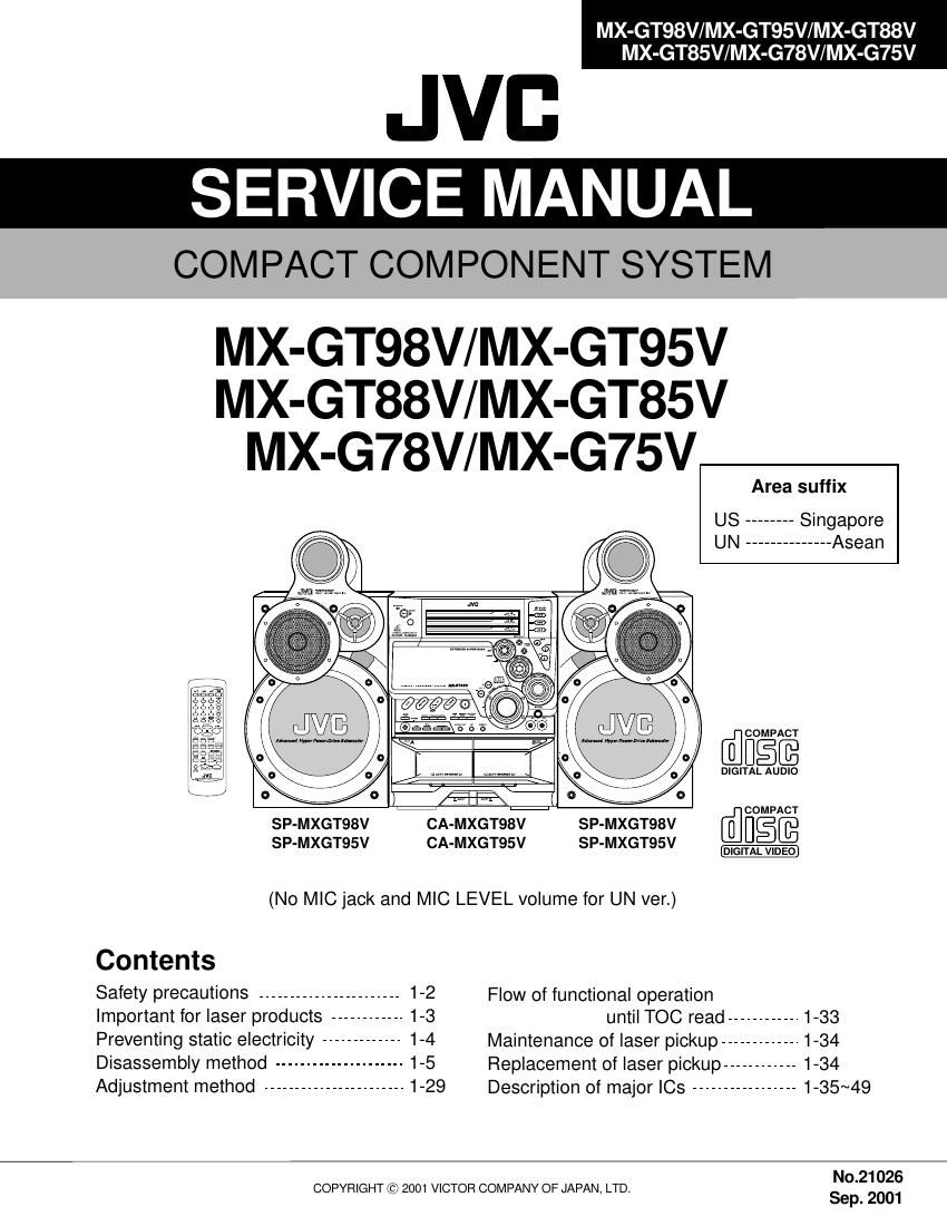
Jvc MXGT 85 V Service Manual

This is the 65 pages manual for Jvc MXGT 85 V Service Manual.
Read or download the pdf for free. If you want to contribute, please mail your pdfs to info@audioservicemanuals.com.

Page: 1 / 65
left right
Jvc MXGT 85 V Service Manual

Extracted text from Jvc MXGT 85 V Service Manual (Ocr-read)


Page 1

MX-GT98V/MX-GT95V/MX-GT88V MX-GT85V/MX-G78V/MX-G75V 1-2 1. This design of this product contains special hardware and many circuits and components specially for safety purposes. For continued protection, no changes should be made to the original design unless authorized in writing by the manufacturer. Replacement parts must be identical to those used in the original circuits. Services should be performed by qualified personnel only. 2. Alterations of the design or circuitry of the product should not be made. Any design alterations of the product should not be made. Any design alterations or additions will void the manufacturer's warranty and will further relieve the manufacture of responsibility for personal injury or property damage resulting therefrom. 3. Many electrical and mechanical parts in the products have special safety-related characteristics. These characteristics are often not evident from visual inspection nor can the protection afforded by them necessarily be obtained by using replacement components rated for higher voltage, wattage, etc. Replacement parts which have these special safety characteristics are identified in the Parts List of Service Manual. Electrical components having such features are identified by shading on the schematics and by ( ) on the Parts List in the Service Manual. The use of a substitute replacement which does not have the same safety characteristics as the recommended replacement parts shown in the Parts List of Service Manual may create shock, fire, or other hazards. 4. The leads in the products are routed and dressed with ties, clamps, tubings, barriers and the like to be separated from live parts, high temperature parts, moving parts and/or sharp edges for the prevention of electric shock and fire hazard. When service is required, the original lead routing and dress should be observed, and it should be confirmed that they have been returned to normal, after re-assembling. 5. Leakage current check (Electrical shock hazard testing) After re-assembling the product, always perform an isolation check on the exposed metal parts of the product (antenna terminals, knobs, metal cabinet, screw heads, headphone jack, control shafts, etc.) to be sure the product is safe to operate without danger of electrical shock. Do not use a line isolation transformer during this check. Plug the AC line cord directly into the AC outlet. Using a "Leakage Current Tester", measure the leakage current from each exposed metal parts of the cabinet, particularly any exposed metal part having a return path to the chassis, to a known good earth ground. Any leakage current must not exceed 0.5mA AC (r.m.s.). Alternate check method Plug the AC line cord directly into the AC outlet. Use an AC voltmeter having, 1,000 ohms per volt or more sensitivity in the following manner. Connect a 1,500 10W resistor paralleled by a 0.15 F AC-type capacitor between an exposed metal part and a known good earth ground. Measure the AC voltage across the resistor with the AC voltmeter. Move the resistor connection to each exposed metal part, particularly any exposed metal part having a return path to the chassis, and measure the AC voltage across the resistor. Now, reverse the plug in the AC outlet and repeat each measurement. Voltage measured any must not exceed 0.75 V AC (r.m.s.). This corresponds to 0.5 mA AC (r.m.s.). 1. This equipment has been designed and manufactured to meet international safety standards. 2. It is the legal responsibility of the repairer to ensure that these safety standards are maintained. 3. Repairs must be made in accordance with the relevant safety standards. 4. It is essential that safety critical components are replaced by approved parts. 5. If mains voltage selector is provided, check setting for local voltage. Good earth groundPlace this probe on each exposed metal part. AC VOLTMETER (Having 1000 ohms/volts, or more sensitivity) 1500 10W 0.15 F AC TYPE ! Burrs formed during molding may be left over on some parts of the chassis. Therefore, pay attention to such burrs in the case of preforming repair of this system. In regard with component parts appearing on the silk-screen printed side (parts side) of the PWB diagrams, the parts that are printed over with black such as the resistor ( ), diode ( ) and ICP ( ) or identified by the " " mark nearby are critical for safety. When replacing them, be sure to use the parts of the same type and rating as specified by the manufacturer. (Except the J&C version)

Page 2

MX-GT98V/MX-GT95V/MX-GT88V MX-GT85V/MX-G78V/MX-G75V 1-3 Important for laser products 1.CLASS 1 LASER PRODUCT 2.DANGER : Invisible laser radiation when open and inter lock failed or defeated. Avoid direct exposure to beam. 3.CAUTION : There are no serviceable parts inside the Laser Unit. Do not disassemble the Laser Unit. Replace the complete Laser Unit if it malfunctions. 4.CAUTION : The compact disc player uses invisible laser radiation and is equipped with safety switches which prevent emission of radiation when the drawer is open and the safety interlocks have failed or are defeated. It is dangerous to defeat the safety switches.5.CAUTION : If safety switches malfunction, the laser is able to function. 6.CAUTION : Use of controls, adjustments or performance of procedures other than those specified herein may result in hazardous radiation exposure. VARNING : Osynlig laserstrålning är denna del är öppnad och spårren är urkopplad. Betrakta ej strålen. VARO : Avattaessa ja suojalukitus ohitettaessa olet alttiina näkymättömälle lasersäteilylle.Älä katso säteeseen.ADVARSEL : Usynlig laserstråling ved åbning , når sikkerhedsafbrydere er ude af funktion. Undgå udsættelse for stråling. ADVARSEL : Usynlig laserstråling ved åpning,når sikkerhetsbryteren er avslott. unngå utsettelse for stråling. Position of labels WARNING LABEL !CAUTIONPlease use enough caution not to see the beam directly or touch it in case of an adjustment or operation check. DANGER : Invisibie laser radiation when open and interlock or defeated. AVOID DIRECT EXPOSURE TO BEAM (e) VARNING : Osynlig laserstrålning är denna del är öppnad och spårren är urkopplad. Betrakta ej strålen. (s) VARO : Avattaessa ja suojalukitus ohitettaessa olet alttiina näkymättömälle lasersäteilylle.Älä katso säteeseen. (d) ADVARSEL :Usynlig laserstråling ved åbning , når sikkerhedsafbrydere er ude af funktion. Undgå udsættelse for stråling. (f) CLASS 1 LASER PRODUCT CLASS 1 LASER PRODUCT

Page 37

MX-GT98V/MX-GT95V/MX-GT88V MX-GT85V/MX-G78V/MX-G75V 1-38 TEN TEOUT TEBPF VDET VCC GND FBAL TBAL GCTLPDLD VREFRFIN RFN 4 5 6 7 8 11 12 13 14 RFOUT RF_EQAGC BDO OFTR 3TENV9 10 15 22 23 21 20 NRFDET SUBT SUBT BCA BCA BCA BCA GCA GCA GCA GCA AMP AMPAMP AMP 19 18 2 VDET 32 31 30 29 27 28 17+ -- +- + - + 1 3 16 25 26 24 - + - + - + - +A B C D E F A + C B + D F ECAGCARF CBDOBDO COFTROFTR 3TOUT CEA NRFDET FEN FEOUT 1.Block diagram 2. Pin function AN22000A-W (IC601) : Digital servo head amp. Pin No. 1 2 3 4 5 6 7 8 9 10Function APC amp. input terminal APC amp. output terminal Power terminal Inversion input terminal for RF addition amplifier RF add amp. output terminal AGC input terminal Capacity connecting terminal for AGC loop filer AGC output terminal Capacity connecting terminal for HPF amplifier 3TENV output terminalPin No. 22 23 24 25 26 27 28 29 30 31 32Function FE amp. reverse input terminal FE amp. output terminal GCTL & APC terminal FBAL control terminal TBALcontrlo terminal Tracking signal input terminal 1 Tracking signal input terminal 2 Focus signal input terminal 4 Focus signal input terminal 2 Focus signal input terminal 3 Focus signal input terminal 1 Pin No. 11 12 13 14 15 16 17 18 19 20 21Function For envelope detection at the dark side of RF BDO output terminal For envelope detection at the blight side of RF OFTR output terminal NRFDET output terminal Ground VRER output terminal VDET output terminal VDET input terminal TE amp. output terminal TE amp. reverse input terminal

Page 48

MX-GT98V/MX-GT95V/MX-GT88V MX-GT85V/MX-G78V/MX-G75V 1-49 1 2 3 4 5 6 7 8 9 10 GND OUT1 P1 VZ IN1 IN2VCC1 VCC2 P2OUT2 Input Output Mode IN1 IN2 OUT1 OUT2 Brake 0 0 0 0 1 0 1 0 0 1 0 1 1 1 0 0 CLOCKWISE COUNTER-CLOCKWISE Brake LB1641 (IC851, IC852) : DC motor driver 1. Pin layout 2. Pin function 12 34 56 78 1. A OUTPUT 2. A-INPUT 3. A+INPUT 4. V 5. B+INPUT 6. B-INPUT 7. B OUTPUT 8. V+- NJM4580L[US ver. only] (IC901) : Mic amp.

Page 50

AB C D E F G 12 3 45 2-1 MX-GT98V/MX-GT95V/MX-GT88V MX-GT85V/MX-G78V/MX-G75V Block diagram FM FRONTEND TU1 FM/DET AM/DET IC 1 MW RF/OSC COIL PLL Synthesizer IC2TUNER MPXCD AUX AUX IN VIDEO OUTMAIN FOCUS/SPINDLE/ FEED/TRACKING BTL DRIVER IC801 SOURCE SELECTOR & E.VOL IC436 MAIN HPF MUTE SYSTEM IC481 INPUT AMP IC 501 HARMONICS GENERATOR IC 502 LPF IC 526 CN870/CN871 CN661 CN504 FW714 CN215 CN205 CN207 CN217 CN706 J81 RELAY RY2 RELAY RY1 SPEAKER TERMINAL POWER AMP IC 701 SUB WOOFER POWER AMP IC602MAIN CN1 CN11 CN801 CN601 CN854 CN855 P011 P001 CN804 CN805 RF & SERVO AMP IC601 DIGITAL SERVO & PROCESSOR IC 651 UNIT MICOM CD CHANGER CONTROL IC 251 L MOTOR DRIVER IC 851 R MOTOR DRIVER IC 852 CN651 CN151 CN101 CN102 IC101 VCD PROCESSOR IC102 EPROM IC103 DRAM IC104 VCD CONPANION CHIP CN860/CN861 CAM0 3 CAM4 7 1SSW 3SSW 1MSW 3MSW A+C B+D E F F T FM SMARFTX CD L CAM R CAM SW1 6 PICKUP TRACKING FOCUS FEEDM MICOM IC 810 FL DISPLAY FL 801 CN880 CN870 CN911 FW901 FW915 FW915 KEY LED SEARCH KNOB LED MAIN VOL WOOFER VOL SOUND MODE KEY LED KEY1,11 CD1LED CD2LED CD3LED SEARCH R,F KEY21,22 VOL KEY2,3,21,32,41,42 KCMND M S TAT KCLK MRDYMPX VOLDA,VOLCK M M FMN-011A FMV-010AM FMB-028-3 FM AM DIGITAL OUTTX SPINDLE M FMB-028-1 FMC-027-1 FMA-006 FMH-031-2 FMH- 031-1 FMB-028-4 FMH-031-3 FMB-028-2 CN315 IF TAPE CN316 CN306 CN305 PB/REC AMP IC302 HEAD SW IC301 SERIAL TO PARALLEL PORT EXTENSION IC303 SOLENOID DRIVE FOR RP MECHA Q3314 Q3315 SOLENOID DRIVE FOR PB MECHA Q3312 Q3313 CN301 CN302 FW301 CN303 CN333 M DRIVER R L R L PB MECHA HEAD RP MECHA HEAD SLCKEY 1~2 SLCKEY1 2 PHOTO A,BSW302 SW306 IC331 SOLENOID SW303 SW304 SW305 SW316 SOLENOID IC332 SLCKEY2 PHB SLCK PHA PB MECHA PP MECHA FMP-007-2 FMP-007-1 MIC JACK 1,2 (Only US) LPF& ECHO MIX IC902 KARAOKE IC446 MIC MIC

Page 55

H AB C DE FG 12 3 45 2-6 MX-GT98V/MX-GT95V/MX-GT88V MX-GT85V/MX-G78V/MX-G75VMX-GT98V/MX-GT95V/MX-GT88V MX-GT85V/MX-G78V/MX-G75V Front key section SHEET 5/9 SHEET 4/9 SHEET 4/9 SHEET 4/9 SHEET 2/9 TW800 FW915 CN870C901 Q956 Q960 Q953 Q918 Q954 Q941 Q940 C1070C935 FW901C1021 C902Q919 JS901 D1003 S901 S902Q920 D1062 S931 S932 S933S951 R930S935C962 C963 JS962 S936 S937 S939 J1001 TW801 S938 L1002 FW713 S952JS956 C960JS960 C961 S950 S942 S944 S943 S945 S949 S948 S947 S946 S915 S917S916R1068 R1021 R1022J1022 J1021 Q1061IC901 C1068 R1069C1066D1061 R1062R1063 D945 D942 D944 D943R955R908 L1003D904 R904 D905 Q901 R929 R954 R951 D954 R938 R941 R932 R933 R935 R940 R939 D940 R931 D941 R937 R953 R952 R936 L1001 C1002C1001C1004 C1006 C1005R916 D953D957 D956 C956 C957 R956 D961 D960 R960 R942 R944 R943 R946R947 R948R949 R945R950D919 R917 D918 D920R919 R920 C1022 C1023VR901 R1071 R1070 C1065 C1067 R1067 R1066 C1063 R1061 C1062 C1061 R1065 R1064 C1064R918 QUB220-15DMHP QUM027-18Z4Z4 0.01 2200p0.01 QUM027-13DGZ41000p 0.01 QSW0911-001 MTZJ2.4B-T2 MTZJ2.4B-T2 10K0.01 0.01 QSW0862-001 QNS0183-001 QUB220-15DMHP QQL231K-470Y QUM153-33DGZ4QSW0912-001 0.01QSW0911-001 0.01 20K 4.7k 4.7kQNS0184-001 QNS0184-001 2SD2144S/VW/-TNJM4580L 0.22/50 1K330P1SS133-T2 12K 390 KTA1267/YG/-TKTA1267/YG/-T KTA1267/YG/-TKRC102M-T KTA1267/YG/-T KTA1267/YG/-T KTA1267/YG/-T1.5KKRC102M-T 5.6K QQR0779-001Z68 L-115XSRD-D-T KRC102M-T2 KRC102M-T 2K 68 2K L-914SRD-T 2.2K 68 2.7K 3.9K 5.6K 68 2.7K L-914SRD-T 2.2K L-914SRD-T 1.5K 68 1.2K 1.2K QQL231K-470Y 3900p 3900p1000p 1000p 1000p1K L-914SRD-TSLA-362LT-T 0.01 0.01 68 SLA-362LT-T 68 3.9K 3.9k 10K2.7K 1.5k1.2k 2.2k 5.6K 1kSLA-362LT-T 1K SLA-362LT-T SLA-362LT-T200 200 1000p 1000pQVQ0299-B54 4.7K 560 150P 2.2/50 56 4.7M 4.7/50 10K 100/10 220/10100 1.5k150P200

Page 61

H AB C DE FG 12 3 45 2-12 MX-GT98V/MX-GT95V/MX-GT88V MX-GT85V/MX-G78V/MX-G75VMX-GT98V/MX-GT95V/MX-GT88V MX-GT85V/MX-G78V/MX-G75V T001C T001C T001C C601C602 C603 C604 C605C606 C607 C608 C609C610 C612 C613 C614 C615 C616C618 C621 C622 C623 C639 C683 C703 C704 C705 C706C707 C708 C709 C710 C711 C712 C713 C714 C715 C716 C721 C722 C723 C726C729 C730 C731 C739 C790 CN705 D619 D620D622 D703D704D719 D723 D724D726 D728 D790 D791 IC602L601 L602 L701 L702 Q601 Q602 Q612 Q613Q680 Q701 Q702 Q710 Q711 Q712 Q713 Q726 Q727 Q728 Q733 Q734 Q735 Q736 Q737 Q790 Q791 Q792 R601R602 R603 R604 R605 R606 R607R608 R613 R614 R615 R616 R617 R618R619 R620 R621R623 R640 R652 R653 R654 R655 R667 R668 R674 R675 R676 R680 R681 R682 R701 R702R703 R704 R705 R707R708 R714 R716 R717 R718 R719 R720 R721R722 R723 R724 R725 R726 R727 R728 R729 R730 R733 R734 R735 R736 R740 R761 R762 R766R768 R769 R774 R775 R776 R777 R778 R786 R787 R790 R791 R792 R793 R794 R795 R796R797R798 R754R753 CN215 R659C625 R658Q604 Q603 R657 BE MAINR A.GND MAINL A.GND S/WIN SMUTE EB BE BE E B B E EB E B E B EB E B E B 1 1B B E BE B B E HPL A.GND HPR E E B EB E 1 L R L E B R FAN[-] FAN[+] EB 14 MAINR MAINL SWR SWL POUT SURR PRT M.GND 12V -VL A.GND VL VH -VH C901 C902D904 D905 JS901Q901 R901 R908 R904 S901 S902 FW901E B 1 77 1FW901 DGNDNC SEARCHLEDF.SEARCH R.SEARCH5VKEY21 C201 C202C203 C204 C205 C211C212 C213 C214 C215 C216 C217 C218 C219 C220 C221 C222 C223 C253 C280 C281 CN201 CN202 CN203 CN205 CN207D201 D202 D204D203 D211 D212 D213 D214 D217 D218 D219 D220 D221 D223 D227 D233 D234 D280 Q201 Q204 Q240 R202 R203 R204R205 R207 R209 R215 R216R217 R218 R242R246R247 R281 R283 R284 CN204 EP201 R210R248R249 R383 R384 R385 C372 Q372 D369 D370 C373 C374 Q371Q374 Q373 R389 CN206 CN2065.6V ECO SURRCTRL SWFB PRT 5.6V 8V 9V -9V 3.3V 10V FL1 FL2 RELAY INH -30V CDD.GND A.GND D.GND M.GND POUT RELAY B2 SWLGND MAINR MRGND MAINL SWRGND SWR MLGND SWLCN207 114 1 10 111 10 1 10 1 1 9V8V 5.6V POUT A.GND M.GNDD.GNDS4 3.3V 10V 1 10 8 101 E B CN205 -VHVH VL P.GND-VL 8VM.GND PRT SURR POUT SWL SWRMAINLMAINR 1 14 NC GND ECO 5.6V 4 1BE B B E E 87 Regulation board Preset/ tuning switch board Amplifer board Regulation & amplifer board