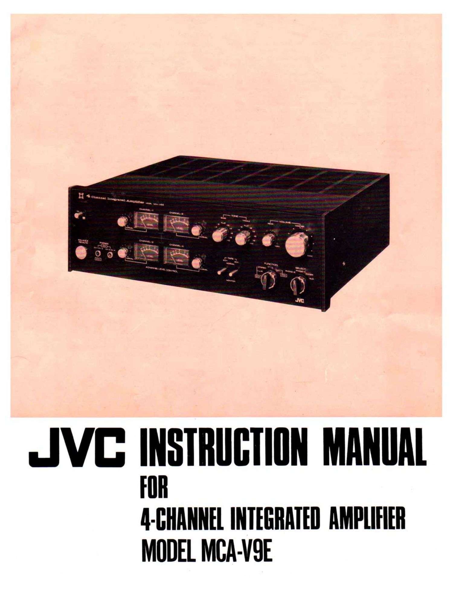
Jvc MCA V9E Owners Manual

This is the 12 pages manual for Jvc MCA V9E Owners Manual.
Read or download the pdf for free. If you want to contribute, please mail your pdfs to info@audioservicemanuals.com.

Page: 1 / 12
left right
Jvc MCA V9E Owners Manual

Extracted text from Jvc MCA V9E Owners Manual (Ocr-read)


Page 2

Line Voltage Adaptation:

Model MCA-V9E is designed to operate on a 50 or 60 Hz power
source 100, 120. 220 or 240 V in line voltage. The line voltage
to which your Model MCA-V9E has been preset is marked on the
tag attached to the power cord. Make sure that the marked
voltage agrees with the line voltage to be supplied before con-
necting the power cord to an AC outlet. If the voltage is different,
adapt y0ur Model MCA-VQE as follows: Loosen the four screws
fixmg the set cover, and remove the cover. (if your Model MCA-
VQE is in a wooden cabinet, loosen the six screws on the bottom
of the cabinet, and remove the cabinet by pulling it forward.) The
AC line voltage selectOr is located near the power transtrmer on
the chassis. By referring to Figs. 2 and 3, reconnect the selectOr
plug so that the arrow on the plug points the voltage marking
conferming to the line voltage to be supplied. The fuse rating
changes according to the AC line voltage. Check the fuse in your
set as follows.

Specific current capacity.
2.3A for 220 volts or 240 volts.
5.0A for 100 volts or 120 volts.

To replace the fuse, turn the cap in the
direction of arrow.

Fig. 1.

Features:

All-stage Direct-coupled OCL Circuitry:

Four completely complementary OCL power amplifiers are built
in. Distortion factor less than 0.1%. More than 25 watts of
power output through each channel. 100 watts in rated overall
output. Specifically designed for 4-channel reproduction. Also
usable for multi-channel amplification, SFCS effect and for driving
two pairs of stereo speakers in 2-channel reproduction.

Double Power Output Through BTL Connection:

By connecting speakers to the 2SPK terminals, Model MCA-V9E
can be operated as a conventional 2-channel stereo amplifier with
a double power output.

4 VU Meters:

Each of the four channels is provided with a separate VU meter
for accurate level adjustment.

SFCS Circuit:

The SFCS (Sound Field Composer System) circuit is built in to
permit reproduction of a 2-channel source similar to that of
4-channel stereo through a four speaker system.

Matrix 4-channel records are also playable.

4-channel DISC Input Terminals:

Through these terminals JVC's 4-channel record can be reproduced.
Auxiliary 4-channel Input Terminals:

A 4-channel tape deck or DISC can be connected here.

4-chennel Record/Play Connectors:

Record/play connectOrs are provided for connection of a 3-head
4~channel tape deck, for example, JVC's Model 1400U.

4-channel Headphone Jacks:

Two headphone jacks are provided far connection of a set of
4-channel headphones. The CH-l/CH-3 jack provides the front
sound and CH-2/CH-4 jack the rear.

Remote Control Terminal:

By connecting JVC's Model 5910 (optional) the level and volume
of all four channels are remote controllable.

Equalizer:

A 3-stage direct-coupled RIAA equalizer of high stability and
low noise is incorporated, using a PNP-PNP-NPN transistor
combination.

Tone Control:

The turnover frequency is 150 Hz for bass and 6 kHz for treble,
with variation characteristics of :10 dB at 50 Hz for bass, and
at 15 kHz for treble. Excellent tone control through a 4-gang
variable resistor with built-in click control levers.

Fig. 2.