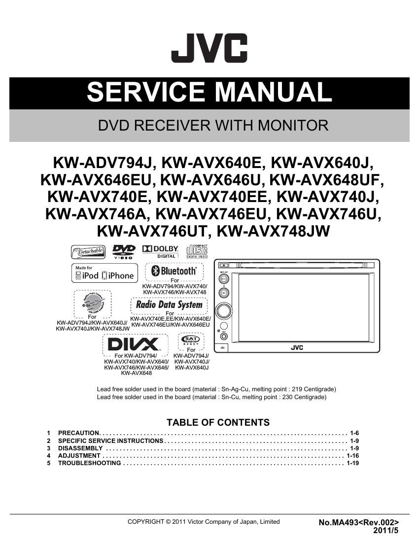
Jvc KWADV 794 J Service Manual

This is the 22 pages manual for Jvc KWADV 794 J Service Manual.
Read or download the pdf for free. If you want to contribute, please mail your pdfs to info@audioservicemanuals.com.

Page: 1 / 22
left right
Jvc KWADV 794 J Service Manual

Extracted text from Jvc KWADV 794 J Service Manual (Ocr-read)


Page 1

1-2 (No.MA493) SPECIFICATION *1 Only for KW-ADV794/KW-AVX748/KW-AVX740 *2 Only for KW-ADV794/KW-AVX740/KW-AVX640. Design and specifications are subject to change without notice. If a kit is necessary for your car, consult your telephone directory for the nearest car audio speciality shop. KW-ADV794J/KW-AVX748JW/KW-AVX740J/KW-AVX640J AMPLIFIER Power Output 20 W RMS × 4 Channels at 4 -„¦ and -‰¤ 1% THD+N Signal-to-Noise Ratio 80 dBA (reference: 1 W into 4 -„¦) Load Impedance 4 -„¦ (4 -„¦ to 8 -„¦ allowance) Equalizer Control Range Level ±12 dB Audio Output Level FRONT OUT, REAR OUT, SUBWOOFER OUT Line-Out Level/Impedance 4 V/20 k-„¦ load (full scale) Output Impedance 1 k-„¦ Video Output (composite) VIDEO OUTColor System PAL/NTSC Video-Out Level/Impedance 1 Vp-p/75-„¦ Other Terminals Input LINE IN, VIDEO IN, CAMERA IN, USB input, MIC IN*1, AUX, Antenna input Others Expansion port*2, OE REMOTE, RGB input FM/AM TUNER Frequency Range FM with channel interval set to 200 kHz 87.9 MHz to 107.9 MHz with channel interval set to 50 kHz 87.5 MHz to 108.0 MHz AM with channel interval set to 10 kHz 530 kHz to 1 700 kHz with channel interval set to 9 kHz 531 kHz to 1 611 kHz FM Tuner Usable Sensitivity 9.3 dBf (0.8 µV/75 -„¦) 50 dB Quieting Sensitivity 16.3 dBf (1.8 µV/75 -„¦) Alternate Channel Selectivity (400 kHz) 65 dB Frequency Response 40 Hz to 15 000 Hz Stereo Separation 40 dB AM Tuner Sensitivity/Selectivity 20 µV/40 dB DVD/CD Signal Detection System Non-contact optical pickup (semiconductor laser) Frequency Response DVD, fs=48 kHz/96 kHz 16 Hz to 22 000 Hz VCD/CD 16 Hz to 20 000 Hz Dynamic Range 93 dB Signal-to-Noise Ratio 95 dB Wow and Flutter Less than measurable limit USB USB Standards USB 2.0 Full Speed Data Transfer RateFull Speed Maximum 12 Mbps Low Speed Maximum 1.5 Mbps Compatible Device Mass storage class Compatible File System FAT 32/16/12 Max. Current DC 5 V 1A BLUETOOTH (Only for KW-ADV794/KW-AVX748/KW-AVX740) Version Bluetooth 2.0 certified Output Power +4 dBm Max. (Power class 2) Service Area Within 10 m (10.9 yd) ProfileHFP (Hands-Free Profile) 1.5 OPP (Object Push Profile) 1.1 A2DP (Advanced Audio Distribution Profile) 1.2 AVRCP (Audio/Video Remote Control Profile) 1.3 PBAP (Phone Book Access Profile) 1.0 MONITOR Screen Size 6.1 inch wide liquid crystal display Number of Pixel 1 152 000 pixels : 800 (horizontal) × 3 (RGB) × 480 (vertical) Drive Method TFT (Thin Film Transistor) active matrix format Color System NTSC/PAL Aspect Ratio 16:9 (wide) GENERAL Power Requirement Operating Voltage DC 14.4 V (11 V to 16 V allowance) Grounding System Negative ground Allowable Storage Temperature -10°C to +60°C (14°F to 140°F) Allowable Operating Temperature 0°C to +40°C (32°F to 104°F) Dimensions (W × H × D) Installation Size (approx.) 182 mm × 111 mm × 160 mm (7-3/16 × 4-3/8 × 6-5/16) Panel Size (approx.) 188 mm × 117 mm × 10 mm (7-7/16 × 4-5/8 × 7/16) Mass (approx.) 2.3 kg (5.1 lbs) (including the Trim plate and Sleeve)

Page 2

(No.MA493)1-3 * Only for KW-AVX740,KW-AVX746 Design and specifications are subject to change without notice.KW-AVX740E/KW-AVX640E/KW-AVX746EU/KW-AVX646EU AMPLIFIER Maximum Power Output Front/Rear 50 W per channel Continuous Power Output (RMS) Front/Rear 20 W per channel into 4 -„¦, 40 Hz to 20 000 Hz at no more than 0.8% total harmonic distortion Load Impedance 4 -„¦ (4 -„¦ to 8 -„¦ allowance) Equalizer Control Range Level ±12 dB Signal-to-Noise Ratio 70 dB Audio Output Level FRONT OUT, REAR OUT, SUBWOOFER OUTLine-Out Level/Impedance4 V/20 k-„¦ load (full scale) Output Impedance1 k-„¦ Video Output (composite) VIDEO OUTColor System PAL/NTSC Video-Out Level/Impedance 1 Vp-p/75 -„¦ Other Terminals Input LINE IN, VIDEO IN, CAMERA IN, USB input, MIC IN*, AUX, Aerial input Others OE REMOTE, RGB input FM/AM TUNER Frequency Range FM 87.5 MHz to 108.0 MHz AM (MW) 531 kHz to 1 611 kHz (LW) 153 kHz to 279 kHz FM Tuner Usable Sensitivity 9.3 dBf (0.8 µV/75 -„¦) 50 dB Quieting Sensitivity 16.3 dBf (1.8 µV/75 -„¦) Alternate Channel Selectivity (400 kHz) 65 dB Frequency Response 40 Hz to 15 000 Hz Stereo Separation 40 dB MW Tuner Sensitivity/Selectivity 20 µV/40 dB LW Tuner Sensitivity 50 µV DVD/CD Signal Detection System Non-contact optical pickup (semiconductor laser) Frequency Response DVD, fs=48 kHz/96 kHz 16 Hz to 22 000 Hz VCD/CD 16 Hz to 20 000 Hz Dynamic Range 93 dB Signal-to-Noise Ratio 95 dB Wow and Flutter Less than measurable limit USB USB Standards USB 2.0 Full Speed Data Transfer Rate Full Speed Maximum 12 Mbps Low Speed Maximum 1.5 Mbps Compatible Device Mass storage class Compatible File System FAT 32/16/12 Max. Current DC 5 V 1A BLUETOOTH (Only for KW-AVX740A/KW-AVX746) Version Bluetooth 2.0 certified Output Power +4 dBm Max. (Power class 2) Service Area Within 10 m ProfileHFP (Hands-Free Profile) 1.5 OPP (Object Push Profile) 1.1 A2DP (Advanced Audio Distribution Profile) 1.2 AVRCP (Audio/Video Remote Control Profile) 1.3 PBAP (Phone Book Access Profile) 1.0 MONITOR Screen Size 6.1 inch wide liquid crystal display Number of Pixel 1 152 000 pixels : 800 (horizontal) × 3 (RGB) × 480 (vertical) Drive Method TFT (Thin Film Transistor) active matrix format Color System PAL/NTSC Aspect Ratio 16:9 (wide) GENERAL Power Requirement Operating Voltage DC 14.4 V (11 V to 16 V allowance) Grounding System Negative ground Allowable Storage Temperature -10°C to +60°C Allowable Operating Temperature 0°C to +40°C Dimensions (W × H × D) Installation Size (approx.) 182 mm × 111 mm × 160 mm Panel Size (approx.) 188 mm × 117 mm × 10 mm Mass (approx.) 2.3 kg (including the Trim plate and Sleeve)

Page 4

(No.MA493)1-5 * Only for KW-AVX746 Design and specifications are subject to change without notice.KW-AVX746A/KW-AVX746U,UT/KW-AVX646U,KW-AVX648UF AMPLIFIER Maximum Power Output Front/Rear 50 W per channel Continuous Power Output (RMS) Front/Rear 20 W per channel into 4 -„¦, 40 Hz to 20 000 Hz at no more than 0.8% total harmonic distortion Load Impedance 4 -„¦ (4 -„¦ to 8 -„¦ allowance) Equalizer Control Range Level ±12 dB Signal-to-Noise Ratio 70 dB Audio Output Level FRONT OUT, REAR OUT, SUBWOOFER OUTLine-Out Level/Impedance4 V/20 k-„¦ load (full scale) Output Impedance1 k-„¦ Video Output (composite) VIDEO OUTColor System PAL/NTSC Video-Out Level/Impedance 1 Vp-p/75 -„¦ Other Terminals Input LINE IN, VIDEO IN, CAMERA IN, USB input, MIC IN*, AUX, Aerial input Others OE REMOTE, RGB input FM/AM TUNER Frequency Range FM 87.5 MHz to 108.0 MHz AM 531 kHz to 1 611 kHz FM Tuner Usable Sensitivity 9.3 dBf (0.8 µV/75 -„¦) 50 dB Quieting Sensitivity 16.3 dBf (1.8 µV/75 -„¦) Alternate Channel Selectivity (400 kHz) 65 dB Frequency Response 40 Hz to 15 000 Hz Stereo Separation 40 dB AM Tuner Sensitivity/Selectivity 20 µV/40 dB DVD/CD Signal Detection System Non-contact optical pickup (semiconductor laser) Frequency Response DVD, fs=48 kHz/96 kHz 16 Hz to 22 000 Hz VCD/CD 16 Hz to 20 000 Hz Dynamic Range 93 dB Signal-to-Noise Ratio 95 dB Wow and Flutter Less than measurable limit USB USB Standards USB 2.0 Full Speed Data Transfer Rate Full Speed Maximum 12 Mbps Low Speed Maximum 1.5 Mbps Compatible Device Mass storage class Compatible File System FAT 32/16/12 Max. Current DC 5 V 1A BLUETOOTH (Only for KW-AVX746) Version Bluetooth 2.0 certified Output Power +4 dBm Max. (Power class 2) Service Area Within 10 m ProfileHFP (Hands-Free Profile) 1.5 OPP (Object Push Profile) 1.1 A2DP (Advanced Audio Distribution Profile) 1.2 AVRCP (Audio/Video Remote Control Profile) 1.3 PBAP (Phone Book Access Profile) 1.0 MONITOR Screen Size 6.1 inch wide liquid crystal display Number of Pixel 1 152 000 pixels : 800 (horizontal) × 3 (RGB) × 480 (vertical) Drive Method TFT (Thin Film Transistor) active matrix format Color System PAL/NTSC Aspect Ratio 16:9 (wide) GENERAL Power Requirement Operating Voltage DC 14.4 V (11 V to 16 V allowance) Grounding System Negative ground Allowable Storage Temperature -10°C to +60°C Allowable Operating Temperature 0°C to +40°C Dimensions (W × H × D) Installation Size (approx.)182 mm × 111 mm × 160 mm 180 mm × 100 mm × 160 mm (KW-AVX648) Panel Size (approx.) 188 mm × 117 mm × 10 mm Mass (approx.) 2.0 kg

Page 8

(No.MA493)1-9 SECTION 2 SPECIFIC SERVICE INSTRUCTIONS This service manual does not describe SPECIFIC SERVICE INSTRUCTIONS. SECTION 3 DISASSEMBLY 3.1 Main body (Used model: KD-AVX740) 3.1.1 Removing the Front chassis (See Fig.1 and 2) (1) Remove the three screws A. (See Fig.1) (2) Disengage two hooks a engaged the Front chassis. (See Fig.1) Fig.1 (3) Remove the four screws B attaching the both side of the Front chassis. (See Fig.2) (4) Disengage two hooks b engaged both side of the Front chassis. (See Fig.2) Fig.23.1.2 Removing the Heat sink (See Fig.3) (1) Remove the three screws C and two screws D attaching the Heat sink. Fig.3 3.1.3 Removing the Rear heat sink (See Fig 4) (1) Remove the two screws E and two screws F attaching the Rear heat sink Fig.4 3.1.4 Removing the DVD mechanism (See Fig.5, 6, 7, 8, 9) (1) Disconnect the card wire from DVD mechanism connected to connector CN105 of the Main board. (See Fig.5) Fig.5 a A b B C D EF CN105

Page 12

(No.MA493)1-13 (4) Remove the five screws A attaching the Top cover assembly. (See Fig. 3) Fig.3 (5) From the bottom side, disconnect the connector wire from Top cover assembly connected to connector CN2 of the Front end board. (See Fig.4) Fig.4 (6) From the bottom side, remove the spring from Traverse mechanism assembly. (See Fig.5) Fig.5 (7 ) From the top side, pull up the traverse mechanism and disengage three dumper positions. (See Fig.6 ) Fig.63.2.2 Removing the Front end board (See Fig.7) (1) Remove the Motor wires from loading motor soldered to TP79 and TP81 of the Front end board. (2) Remove the two screws B attaching the Front end board. Fig.7 3.2.3 Removing the Loading arm assembly (See Fig.8) (1) Remove the Loading arm spring L from Loading arm assembly. (2) Slide to left side and then disengage hook a then hook b. Fig.8 3.2.4 Removing the Gear base assembly (See Fig.9, 10) (1) Remove the Loading arm spring L. (See Fig.9) Fig.9 A CN2 Dumper (Different color sprin BB TP79TP81 Loading arm assembly Loading arm spring Lhook a hook b Loading arm spring L

Page 21

(No.MA493) VSE Printed in Japan Victor Company of Japan, Limited Mobile Entertainment Division 2967-3, Ishikawa-machi, Hachioji-shi, Tokyo, 192-8525, Japan