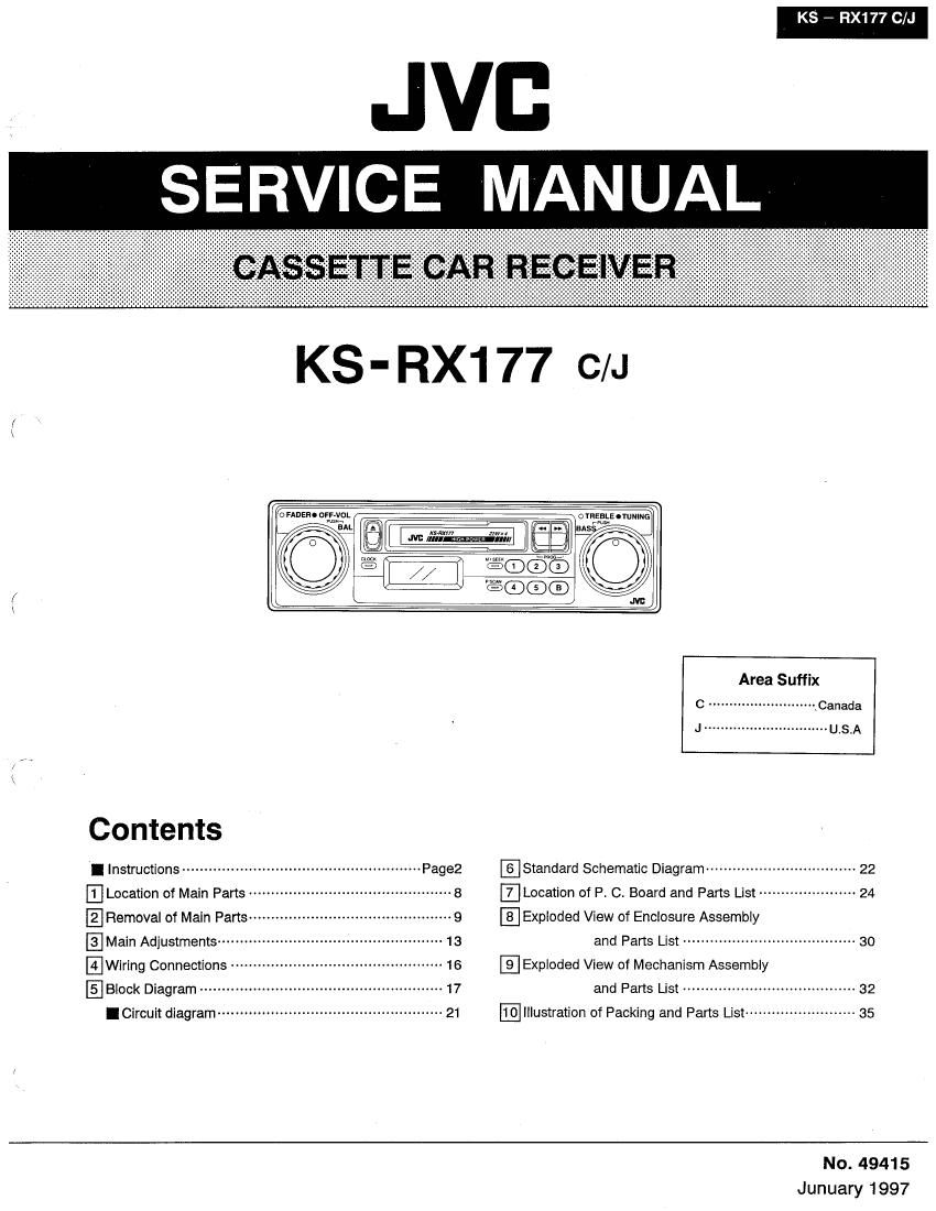
Jvc KSRX 177 Service Manual

This is the 42 pages manual for Jvc KSRX 177 Service Manual.
Read or download the pdf for free. If you want to contribute, please mail your pdfs to info@audioservicemanuals.com.

Page: 1 / 42
left right
Jvc KSRX 177 Service Manual

Extracted text from Jvc KSRX 177 Service Manual (Ocr-read)


Page 1

KS - RX177 C/J

JVD
SERVICE MANUAL

KS - RX1 77 C/J

tc: FADEBC OFF- VOL

.9


l
/ i
O / "scam J \J

7M

Area Suffix

C .......................... .Canada

J .............................. USA
Contents
I Instructions -------------------- @Standard Schematic Diagram ~~~~~~~~~~~~~~~~~~~~ 22
Location of Main Parts ----- .Location of P C. Board and Pans List ------ 24
E} Removal of Main Paris ---------------------------------------------- 9 Exploded View of Enclosure Assembly
@Mam Adjustments ------------ 13 and Parts List --------------------------------------- 30
.Wiring Connections --------- E] Exploded View of Mechanism Assembly
EBIOCK Diagram ....................................................... 17 and Parts List ....................................... 32

I Circuit diagram --------------------------------------------------- 21 Illustration of Packing and Parts List ------------------------ 35
No. 4941 5

Junuary 1997

Page 2

KS - RX177 C/J

A CAUTION

Burrs formed during molding may be left over on some parts of the chassis. Therefore,
pay attention to such burrs in the case of preforming repair of this system.

JVD

//

CASSETTE RECEIVER KS-RX177

KS-RX1 77

ornaefi-rumuow

For Customer Use:

Enter below the Model No. and
Serial No. which are located on the
top or bottom at the cabinet. Retain
this inlormation for luture reference.

INSTRUCTIONS Model No.
Serial No.
J version
K SPECIFICATIONS
AUDIO AMPLIFIER SECTION (FM Tuner) GENERAL

Maximum Power Output: (Front) 22 Watts per channel
(Rear) 22 watts per channel
Continuous Power Output (HMS): (Front) 8 watts per
channel into 4 n, 40 to 20.000 Hz at no more than
0.8% total harmonic mstonion. (Rear) 8 watts per
channel into 4 o. 40 to 20,000 Hz at no more than
0.3% total hamtonlc distortion.
Load Impedance: 4 fl (4 - 8.0 Allowable)
Tone Control Range
Bass: 210 dB at 100 Hz
Treble: :10 dB at 10 kHz
Frequency Response: 40 - 20,000 Hz
Signal-to-Noise Ratio: 60 dB

RADIO SECTION
Frequency Flange
FM: 87.5 - 107.9 MHz
AM: 530 - 1.710 kHz

Usable Sensitivity: 15.3 dBl (1.6 w/75 0) Power Raquirement:
50 as Ouieting Sensitivity: 13.3 dBi (2.4 "W75 9) Operating Voltage: 0014.4 V m V - 16 V
Alternate Channel Setectivity (400 kHz): 65 d8 Allowable)
Frequency Response: 40 - 15,000 Hz Grounding System: negative Ground
Stereo Separation: 35 dB Dimensions (W x H x D)
Capture Ratio: 2.0 dB Chassis: 178 x 50 x 134 mm
(AM Tuner) (7-1/16 x 2" X 55/16")
Sensitivity; 20 uV Nosepiece: 105 x 42 x 35 mm
Selectivity: 35 dB (43/16" x1»1l/16" x 1-7116")
CASSETTE DECK SECTION Control Shaft Pitch: 148 mm (5-7/8I
Wow 8 Flutter: 0.15 % tWRMS) Gross Weight: 1.5 kg (3.4 lbs)
Fast Wind Time: 190 sec. lC-GOl
Frequency Response:

50 - 14,000 Hz (is dB)
Signal-to»Noise Ratio: 52 dB
Stereo Separation: 40 dB

Design and specifications sub/'ect to change with-
out notice.

If a kit is necessary for your car, consult your
telephone directory for the nearest car audio
speciality shop.

2 (No. 49415)

/"\

/\

Page 12

KS - RX177 ClJ

Remove the E washer Ramfive the E WaSher

O Replacing the head/pinch roller assembly. and pinch roller and pinch roller
0 Pinch roller. (See Fig. 2-16) Plae
1. Remove the E washer © on the pinch roller shaft.


Thins ring Thickspring
2. Remove the pinch roller spring from the chassis and

pull out the pinch roller assembly.
0 Head assembly. (See Fig. 2-16)
1. Remove the head mounting screw (AD.
2. Remove the C washer (5) to pull out the collar. Pinch roller spring
3. Remove the plate to remove the springs and head.

Pinch roller spring
Remove the spring from the chassis

(The left and right springs are different.)
0 Motor (See Fig. 2-17) 9- 2-16
1. Remove the main belt (capstan belt)/sub~ belt. Main be"
2. Remove the two motor mounting screws (63.
~k Sub- belt changing method.
1. Remove the main belt.
2. Remove the sub- belt from the motor pulley.
3. Remove the three reel base unit mounting screws ®
andloosen one Q.
4. Lift up the reel base slightly to change the belt.
0 Reel base unit (See Fig. 2~17-2-19)
1, Remove select link B rod at the top front by turning the rod

near the pinch roller as shown in the figure.
Reel base unit

2, Remove the four reel base unit mounting screws ® and O. F' 2 17
lg. -

3.Remove the reel base unit carefully. (Note: service for the
reel base unit is not available.)

Pinch roller

Inside view of the reel base unit

12 (No. 49415)

,e.