Jvc KSLX 200 R Service Manual

This is the 50 pages manual for Jvc KSLX 200 R Service Manual.
Read or download the pdf for free. If you want to contribute, please mail your pdfs to info@audioservicemanuals.com.

Page: 1 / 50
left right
Jvc KSLX 200 R Service Manual

Extracted text from Jvc KSLX 200 R Service Manual (Ocr-read)


Page 1

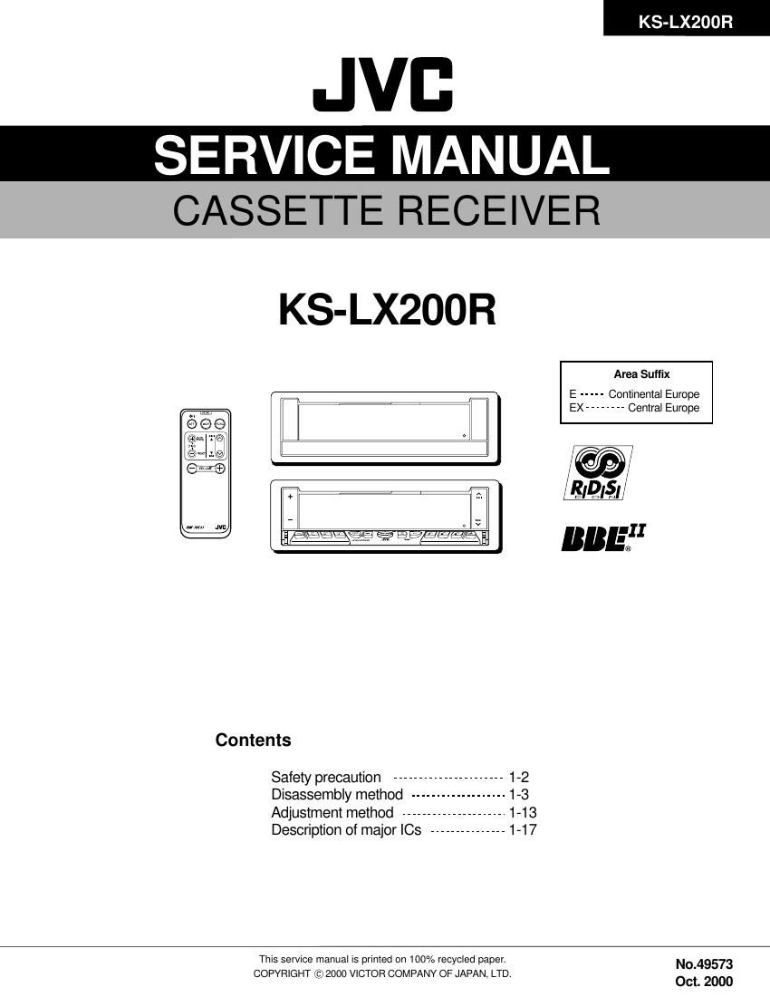
KS- LX200 R

JVB
SERVICE MANUAL

CASSETTE RECEIVER

KS- LX200R

Area Suffix

E ----- Continental Europe
EX -------- Central Europe

r@i

r

ilk/DIS] /

"n :11

Contents
Safety precaution ...................... 1-2
Disassembly method ................... 1-3
Adjustment method ..................... 1-13
Description of major ICs ............... 1.17
This service manual is printed on 100% recycled paper. [10-49573

COPYRIGHT if 2000 VICTOR COMPANY OF JAPAN, LTD.
1 Oct. 2000

Page 2

KS-LX200R

Safety precaution

A CAUTION Burrs formed during molding may be left over on some parts of the chassis. Therefore,
pay attention to such burrs in the case of preforming repair of this system.

Page 11

lFtemoving the sub motor
(See Fig.4 and 6)

- Prior to performing the following procedure, remove
the connector board and the load arm assembly.

1. Remove the slit washer] and the worm gear.

2. Remove the two screws F.

lRemoving the play head / pinch roller
assembly (twin set) (See Fig.7)
- Prior to performing the following procedure, remove
the connector board, the load arm assembly and the
sub chassis.

1. Remove the spring K retaining the play head
assembly and pull out the play head assembly.

2. Remove the two screws G.
3. Remove the two slit washers | attaching the pinch

roller assembly (twin set). Pull out each pinch roller
assembly.

KS-LX200R

Slit washerj

Worm gear
Sub motor

Pinch roller assembly Pinch roller assembly

G

Spring k h

" CD"
(9 .
I
(22"
Spring k

Fig.7

Page 19

KS-LX200R

Pin No. Symbol l/O Functions
15 NRSW | Dolby NR control L:NR OFF H:NR ON
17 INSW | Line amplifier input select control L:TAPE IN H:AUX [N
18 METAL | Playback equalizer amplifiercontrol L:120us H:70us
19 DRSW | Head select control L:FORWARD H:REVERSE
20 FF/REW | Music sensor mode control Low(open):G1 Higth2
21 MSSW | Music sensor control Low(open):MS on HigthS OFF
22 NC - Non connection
23 TCH2 - Time constant for the HLS
24 LlNEOUT2 0 Line output
25 DIREF - Resistance for setting the reference current (Connects 20(18)KQ
between DIREF pin and GND for the standard setting.)
25 NC - Non connection.
27 TAPEIN2 I TAPE input.
28 GND - To ground.
29 PBOUT2 O Playback equalizer amplifier output.
30 PBEQ2 0 Resistance for selecting the playback equalizer amplifier time constant
31 PBFB2 l Playback equalizer amplifier feedback.
32 NC - Non connection.
33 PBREF2 O Playback equalizer amplifier reference (Vcc/2 output)
34 PBFIN2 | Playback equalizer amplifier input (FORWARD head connected)
35 VCT 0 Center (Vcc/2 output)
35 PBGND - Playback equalizer amplifier ground (Connect to ground)
37 PBFIN1 l Playback equalizer amplifier input (FORWARD head connected)
33 PBREF1 O Playback equalizer amplifier reference (Vac/2 output)
39 NC - Non connection.
40 PBFB1 l Playback equalizer amplifier feedback.

I NJM4565M-W (IC951,|C171,|C323) : Ope amp.

O

A OUTPUT E

A -|NPUT 2

EV+

E B OUTPUT

E B -|NPUT

E B +|NPUT