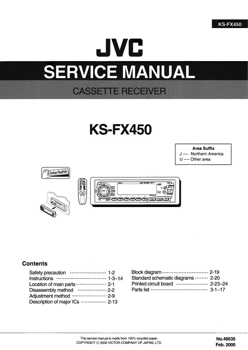
Jvc KSFX 450 Service Manual

This is the 64 pages manual for Jvc KSFX 450 Service Manual.
Read or download the pdf for free. If you want to contribute, please mail your pdfs to info@audioservicemanuals.com.

Page: 1 / 64
left right
Jvc KSFX 450 Service Manual

Extracted text from Jvc KSFX 450 Service Manual (Ocr-read)


Page 1

KS-FX450

JVB
_SERV'CE MANUAL

KS-FX450

Area Suffix
J ---- Northern America
U Other area

Contents
Safety precaution ---------------------- 1-2 Block diagram ---------------------------- 2-1 9
Instructions -------------------------- 1-3~14 Standard schematic diagrams -------- 2-20
Location of main parts ------------------- 2-1 Printed circuit board ------------------- 2-23~24
Disassembly method ------------------ 2-2
Adjustment method ------------- 2-9
Description of major ICs ---------------- 2-13

This sen/ice manual is made from 100% recycled paper N°_49535

COPYRIGHT © 2000 VICTOR COMPANY OF JAPAN. LTD. Feb 2000

Page 2

KS-FX450 #1

Safety precaution

A CAUTION Burrs formed during molding may be left over on some parts of the chassis. Therefore,
pay attention to such burrs in the case of preforming repair of this system.

Page 7

6

[ Using the Sound Control Memory VJ

You can Salem and store a preset sound adlusmsnt suitable to each playback source,
(Advanced soul

ENGLISH

Selecting and storing the sound modes

Once you select a sound mode, it is stored in memory, and will be recalled every time you

selecl the same source. A sound mode can be stored each ol the lollowlng sources 7 FMI.

FM2, FMS, AM, tape, and external components.

- Il you do not want to store the sound mode eeperatelylor each playback source, bul went to
use the same sound mode tor all the sources, see "Cancellng Advanced sow on page at.

71an lrtdleeler

Each tlme you press the button, Illa sound made changes as lollows:

ISL-MUN: BERT SUFTQFUP]

- ll the Link" lrrdlcetor is lll on the display lwrth 30M LlNK sel tn "LINK
ON 7 see page 21). the selected sound mode can be stored in
memery tor the current source, and the allecl applies to the current
source.

- ll lhe Link indicator ls not In on the display [wntl SCM LINK set to
LINK OFF"). lhe selected seuhd mode ellect applles Io any source.

a Select the sound mode you want.

Indication For: PIS! vlluu

Bass Treble Loudness
SCM OFF (Flat sound) 00 00 On
BEAT Rock or mean musrc ma 00 On
SOFT Quiet background "1le +01 4m 0"
POP Light music +04 901 O"

6

[ Storing your own sound adjustments ]

Ybu can adjust the sound modes (BEAT, SOFT, FOP: see page 16) to your nmlerence and
store your own adjustmerlls In memory,

ENGLISH

l
3 Call up the sound mode you want to adjust,
See page Is lor delalls.
5 Within

2

To adjust the bass or treble sound level
Select BAS or TRE ~

To turn on or oil the loudness function
See page 15 lot dolails,

Adjust the bass or treble level.
See page M to: detalls

Press and hold SCM (Sound Control Memory)
% unlil the sound mode you have selected

flashes on the display.
vour selllng ls stored ln memory,

Repeat the same procedure to store other settings.

To reset lo the factory settings
8 Repeat the same procedure and leasslgn the preset mlues Ilsted tn the table on page 16,

KS- FX450

Recalling the sound modes \

ENGLISH

Source billions

The Llnk' indicator starts llashlng, find "16 sound mode stored
in memory tor the selected source ls recalled.

Select the source while the Link" indicator is
5" %- lil on the display.

< 8"!" 5,
= \
% Fl CTEIEZQfi

Eouallzelron pattern at lhe
selected sound mode appears.

Notes:

. You run all/ml mu mum! rruul.» I4! Wul prrfrmm r, uru/ \mn' u m lrlemvry.
will wan! to adjlm and rim-1' wurmrxirullruulld rnndr. m xlrrrirrg wrur llwn urunu ud/mmlwlll "
rm [Inga m.

- TmltljllllIhrbtllrundlrrhlr rum/n -
m pugel to (WI I5 (lruur all/ulrmu

errr/mlt urltllum oli/(fllheloluln .r/unuunr. lampnnlrlly,
wlll I» mauled lfwluthw luuru u tern-led)


17
OTHER MAIN FUNCTIONS m
[ Setting the clock J §
4
(I)
2
rd
2,3
1,4 DISP
Press and hold SEL (Select) for more than 2 seconds
so that one 01 the PSM items appears on the display.
Set the hour.
El Select CLOCK H (Hour)" if not
shown on the display.
E Adjust the hour.
Set the minute.
l H Select CLOCK M (Minute)."
l2l Adjust the minute.
4 , , .
Flnlsh the setllng.
To check Ihe current clock time [changing the displcy mode)
Press DIsP repeatedly Each tlme you press the punch, the dlsplay mode changes as follows:
nurlnll tuner womlun: ounng Ilpn opentlon:
Enid e-e one we H one.
During co enungureperntlon: nunng extent-l component wot-marl:
DI»: numbu H Clock CIOCk fluvial! Ind dlllpmrl Immmw.
' it the unit l5 not In use when you press DISP, the power turns on, the clock time is shown tor
5 seconds, lnen the power lums oil 19

1-7

Page 23

Adjustment method

lTest instruments required for adjustment
1. Digital oscilloscope(100MHz)
2. Frequency Counter meter
3. Electric voltmeter
4. Wow & flutter meter
5. Test Tapes

MC-109C ----- For TAPA CURL confirmation
(without Padd type)
V l 724 ------------------- For DOLBY level measurement

VT739 .. For playback frequency measurement
VT712 For wow flutter & tape speed measurement
\fl703 ..................... For head azimuth measurement
6. Torque gauge .................... Cassette type for CTG-N

(mechanism adjustment)

I Measuring conditions(AmpIifier section)

Power supply voltage .............. DC14.4V (10.5 - 16V)
Load impedance ........... 4 (ZSpeakers connection)
Line out ............................................................ 20k

KS- FX450

lStandard volume position
Balance and Bass,TrebIe volume .Fader
:Center(lndication0")
Loudness,Dolby NR,Sound,Cruise:Ofl
Volume position is about 2V at speaker output with
following conditions, Playback the test tape VT721.
AM mode 1000kHfl62dB,INT/400Hz,30%
modulation signal on receiving.
FM mono mode 97.5MHz/66dB,lNT/400Hz,22.5kHz
deviation pilot off mono
FM stereo mode 1kHz,67.5kHz dev. pilot7.5kHz dev.
Output level OdB(1 V,50 /open terminal)

2-9

Page 24

KS- FX45O

I Arrangement of adjusting & lest points

Cassette mechanism
(Surface)

Motor assembly


Azimuth screw A

Tape speed adjust
(Forward)

Playback head

Azimuth screw B
(Reverse)

Head section view

Azimuih screw B Azimuth screw A
(Reverse) (Fen/ward)

Playback Head

2-10