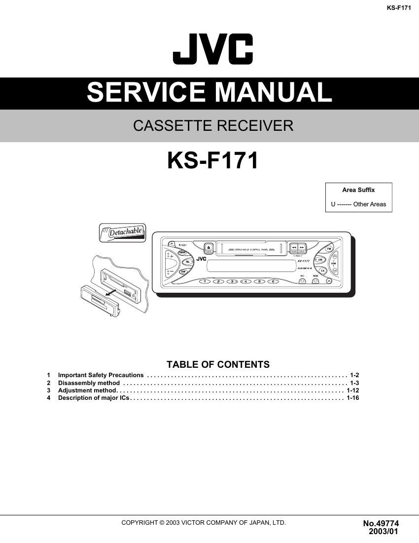
Jvc KSF 171 Service Manual

This is the 24 pages manual for Jvc KSF 171 Service Manual.
Read or download the pdf for free. If you want to contribute, please mail your pdfs to info@audioservicemanuals.com.

Page: 1 / 24
left right
Jvc KSF 171 Service Manual

Extracted text from Jvc KSF 171 Service Manual (Ocr-read)


Page 1

KS-F171 1-2 (No.49774) SECTION 1 Important Safety Precautions 1.1 Safety Precautions ! Burrs formed during molding may be left over on some parts of the chassis. Therefore, pay attention to such burrs in the case of preforming repair of this system.

Page 2

KS-F171 (No.49774)1-3 SECTION 2 Disassembly method 2.1 Main body 2.1.1 Removing the front panel assembly (See Fig.1) (1) Press the release button and remove the front panel as- sembly. Fig.1 2.1.2 Removing the bottom cover (See Fig.2) - Prior to performing the following procedure, remove the front panel assembly. (1) Turn the body upside down. (2) Insert a screwdriver under the joints to release the two joints a on the left side, the two joints b on the right side and the joint c on the back of the body, then remove the bottom cover from the body. CAUTION: When releasing the joint c using a screwdriver, do not damage the board. Fig.2 2.1.3 Removing the front chassis (See Fig.3) - Prior to performing the following procedure, remove the front panel assembly and bottom cover. (1) Remove the screw A on each side of the body. (2) Release the two joints d and the two joints e on the sides, then remove the front chassis toward the front. Fig.3 Front panel assembly Release button Bottom cover Joint b Joint b Joint c Joint a Joint a Joint d Front chassis A Joint e Joint d Joint e

Page 18

KS-F171 (No.49774)1-19 - Pin functions Pin No Symbol Function 1 DI Serial data input terminal for control 2 CE Chip enable terminal 3 VSS GND 4 LROUT Rear Lch fader output terminal 5 LFOUT Front Lch fader output terminal 6 LFIN Front Lch input terminal 7 LOUT C & R connection terminal for super bass band 8 LSB C & R connection terminal for super bass band 9 LBASS2 C & R connection terminal for bass band 10 LBASS1 C & R connection terminal for bass band 11 LTRE Capacitor connection terminal for treble band filter 12 LIN Lch input terminal 13 LSELO Input selector output terminal 14 L5 input signal terminal 15 L4 input signal terminal 16 L3 input signal terminal 17 L2 input signal terminal 18 L1 input signal terminal 19 Vref Power supply for analog GND 20 R1 input signal terminal 21 R2 input signal terminal 22 R3 input signal terminal 23 R4 input signal terminal 24 R5 input signal terminal 25 RSELO Input selector output terminal 26 RIN Rch input terminal 27 RTRE Capacitor connection terminal for treble band filter 28 RBASS1 C & R connection terminal for bass band filter 29 RBASS2 C & R connection terminal for bass band filter 30 RSB C & R connection terminal for super bass band filter 31 ROUT C & R connection terminal for super bass band filter 32 RFIN Rch input terminal 33 RFOUT Front Rch fader output terminal 34 RROUT Rear Rch fader output terminal 35 VDD Power supply terminal 36 CL Serial clock output terminal for control