Jvc KDSX 950 Service Manual

This is the 72 pages manual for Jvc KDSX 950 Service Manual.
Read or download the pdf for free. If you want to contribute, please mail your pdfs to info@audioservicemanuals.com.

Page: 1 / 72
left right
Jvc KDSX 950 Service Manual

Extracted text from Jvc KDSX 950 Service Manual (Ocr-read)


Page 1

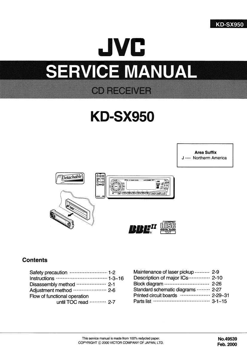
KD-SX950

JVB
,, SERV'CE MANUAL ,

KD-SX950

Area Suffix
J Northerm America


Contents

Safety precaution ----------------------- 1-2 Maintenance of laser pickup --------- 2-9
Instructions ------------------------ 1-3~16 Description of major ICs ----- 2-10
Disassembly method --------- 2-1 Block diagram --------------------------- 2-26
Adjustment method -------------------- 2-6 Standard schematic diagrams -------- 2-27

Flow of functional operation Printed circuit boards ------------------ 2-29~31

until TOC read ---------- 2-7 Parts "St """"""""""""""""""" 3'1 "15
This service manual is made from 100% recycled paper No_49539

COPYRIGHT © 2000 VICTOR COMPANY OF JAPAN, LTD. Feb 2000

Page 2

KD-SX950 j

Safety precaution

1-2

& CAUTION Burrs formed during molding may be left over on some parts of the chassis. Therefore,
pay attention to such burrs in the case of preforming repair of this system.

A CAU110N Please use enough caution not to see the beam directly or touch it in case of an
adjustment or operation check.

Page 30

KD-SX950

I T09462F (IC521) : DSP & DAC

1 .Pin Layout

2.Pin Function (1/2)

Pin No. Symbol I/O Function
1 TESTO I Test mode terminal. Normally, keep at open
2 H80 0 Playback speed mode flag output terminal
3 UHSO O Playback speed mode flag output terminal
4 EMPH 0 Sub code 0 data emphasis flag output terminal. "H=ON L"=OFF
5 LRCK 0 Channel clock output terminal.(44.1kHz) "H"=Rch "L"=Lch
6 Vss - Digital GND terminal
7 BCK 0 Bit clock output terminal. (1 .4122MH2)
8 AOUT 0 Audio data output terminal
9 DOUT 0 Digital data output terminal
10 MBOV O Buffer memory over signal output terminal.
11 IPF 0 Correction flag output terminal
12 SBOK 0 Sub code 0 data CFlCC check adjusting result output terminal. "H"=result OK
13 CLCK l/O Sub code P~W data readout input/output terminal
14 Vdd - ggital power supply voltage terminal
15 V35 - Digital GND terminal
16 DATA 0 Sub code P~W data output terminal
17 SFSY O Play-back frame sync signal output terminal
18 SBSY 0 Sub code block sync signal output terminal
19 SPCK 0 Processor status signal readout clock output terminal
20 SPDA 0 Processor status signal output terminal
21 COFS 0 Correction frame clock output terminal (7.35kHz)
22 MoN|T 0 Internal signal (DSP internal flag and PLL clock) output terminal
23 Vdd - Digital power supply voltage terminal
24 TESIOO I Test input/output terminal. Normally, keep at L level
25 P2VREF - PLL double reference voltage supply terminal
26 HSSW O 2/4 times speed at "Vref" voltage
27 ZDET O 1bit DA converter zero detect flag output terminal
28 PDO 0 Phase difference signal output terminal of EFM signal and PLCK signal
29 TMAXS O TMAX detection result output terminal. Selected by command bit (TMPS)
3O TMAX O TMAX detection result output terminal. Selected by command bit (TMPS)
31 LPFN I LPF amplifier inverting input terminal for PLL
32 LPFO 0 LPF amplifier output terminal for PLL
33 PVFIEF - PLL reference voltage supply terminal
34 VCOFIEF l VCO center frequency reference level terminal
35 VCOF O VCO filter terminal
36 AVss - Analog GND terminal
37 SLCO 0 Data slice level output terminal
38 RH I RF signal input terminal
39 AVDD - Analog power supply voltage terminal

2-14