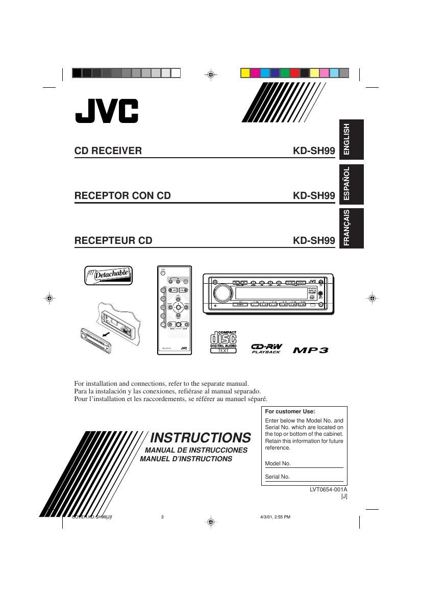
Jvc KDSH 99 Owners Manual

This is the 132 pages manual for Jvc KDSH 99 Owners Manual.
Read or download the pdf for free. If you want to contribute, please mail your pdfs to info@audioservicemanuals.com.

Page: 1 / 132
left right
Jvc KDSH 99 Owners Manual

Extracted text from Jvc KDSH 99 Owners Manual (Ocr-read)


Page 1

2 ENGLISH INFORMATION (For U.S.A.) This equipment has been tested and found to comply with the limits for a Class B digital device, pursuant to Part 15 of the FCC Rules. These limits are designed to provide reasonable protection against harmful interference in a residential installation. This equipment generates, uses, and can radiate radio frequency energy and, if not installed and used in accordance with the instructions, may cause harmful interference to radio communications. However, there is no guarantee that interference will not occur in a particular installation. If this equipment does cause harmful interference to radio or television reception, which can be determined by turning the equipment off and on, the user is encouraged to try to correct the interference by one or more of the following measures: Ð Reorient or relocate the receiving antenna. Ð Increase the separation between the equipment and receiver. Ð Connect the equipment into an outlet on a circuit different from that to which the receiver is connected. Ð Consult the dealer or an experienced radio/TV technician for help. IMPORTANT FOR LASER PRODUCTS Precautions: 1. CLASS 1 LASER PRODUCT 2.DANGER: Invisible laser radiation when open and interlock failed or defeated. Avoid direct exposure to beam. 3.CAUTION: Do not open the top cover. There are no user-serviceable parts inside. Leave all servicing to qualified service personnel. 4.CAUTION: This CD player uses invisible laser radiation, however, is equipped with safety switches to prevent radiation emission when unloading CDs. It is dangerous to defeat the safety switches. 5.CAUTION: Use of controls, adjustments or performance of procedures other than those specified herein may result in hazardous radiation exposure. BEFORE USE *For safety....¥ Do not raise the volume level too much, as this will block outside sounds, making driving dangerous. ¥ Stop the car before performing any complicated operations.* Temperature inside the car....If you have parked the car for a long time in hot or cold weather, wait until the temperature in the car becomes normal before operating the unit. How to reset your unit Press the reset button on the front panel using a ball-point pen or similar tool. Note: Your preset adjustments Ð such as preset channels or sound adjustments Ð will be erased. CAUTION: NEVER insert your finger in between the control panel and the unit, as it may get caught or hurt. (See page 29.) EN02-04.KD-SH99[J]f4/3/01, 2:55 PM 2

Page 2

3 ENGLISH CONTENTS Thank you for purchasing a JVC product. Please read all instructions carefully before operation, to ensure your complete understanding and to obtain the best possible performance from the unit. How to reset your unit ............................... 2 LOCATION OF THE BUTTONS ............ 4 Control panel ........................................... 4 Remote controller .................................... 5 Preparing the remote controller ................ 6 BASIC OPERATIONS ...................... 7 RADIO BASIC OPERATIONS ............. 8 Listening to the radio ................................ 8 Storing stations in memory ....................... 9 Tuning into a preset station ...................... 10 CD OPERATIONS .......................... 11 Playing a CD ............................................ 11 Locating a track or particular portion on a CD ................................................. 12 Selecting CD playback modes .................. 12 Playing a CD Text .................................... 13 Prohibiting disc ejection ............................ 13 MP3 INTRODUCTION ..................... 14 What is MP3? .......................................... 14 How are MP3 files recorded and played back? ......................................... 14 MP3 OPERATIONS ........................ 16 Playing an MP3 disc ................................. 16 Locating a file or particular portion on an MP3 disc ..................................... 17 Selecting MP3 playback modes ............... 20 SOUND ADJUSTMENTS .................. 21 Adjusting the sound ................................. 21 Reinforcing the bass sound ...................... 21 Selecting preset sound modes ................. 22 Storing your own sound adjustments ....... 23 OTHER MAIN FUNCTIONS ............... 24 Setting the clock ...................................... 24 Changing the general settings (PSM) ...... 24 Assigning names to the sources .............. 28 Changing the control panel angle ............. 29 Detaching the control panel ...................... 30 EXTERNAL COMPONENT OPERATIONS .. 31 Playing external components ................... 31 CD CHANGER OPERATIONS ............. 33 Playing CDs ............................................. 33 Selecting CD playback modes .................. 34 ADDITIONAL INFORMATION ............. 35 TROUBLESHOOTING ...................... 36 MAINTENANCE ............................ 38 Handling discs ......................................... 38 SPECIFICATIONS .......................... 39 CAUTION on Volume Setting CDs produce very little noise compared with other sources. If the volume level is adjusted for the tuner, for example, the speakers may be damaged by the sudden increase in the output level. Therefore, lower the volume before playing a disc and adjust it as required during playback. About the demonstration mode (DEMO MODE)... When shipped from the factory, ÒDEMO MODEÓ is set to ÒDEMO ONÓ in this unit. The following demonstration, introducing the main features equipped with this unit, will appear on the display automatically if no sound comes in for 3 minutes. (See page 27.) ¥MP3: (Enables you to play MP3 discs.) ¥24bit DAC: (24 bit digital-analog converter: Gives you a high quality sound after D/A conversion.) ¥HS TUNER: (High-sensitivity Tuner: Enables a fine reception of stations.) ¥EQUALIZER: (Enables you to fine-adjust the sound to match your preference.) ¥SUB WOOFER: (Enables you to connect a subwoofer and to adjust its output level.) EN02-04.KD-SH99[J]f4/3/01, 2:55 PM 3

Page 82

39 FRAN-AIS SECTION AMPLIFICA TEUR AUDIO Puissance de sortie maximum: Avant: 50 W par canal Arrire: 50 W par canal Puissance de sortie en mode continu (RMS): Avant: 19 W par canal pour 4 W, 40 Hz ˆ 20 000 Hz ˆ moins de 0,8% de distorsion harmonique totale. Arrire: 19 W par canal pour 4 W, 40 Hz ˆ 20 000 Hz ˆ moins de 0,8% de distorsion harmonique totale. ImpŽdance de charge: 4 W (4 W ˆ 8 W tolŽrŽs) Plage de commande de lÕŽgaliseur: LOW: ±12 dB (50 Hz, 80 Hz, 120 Hz) MID: ±12 dB (700 Hz, 1 kHz, 2 kHz) HIGH: ±12 dB (8 kHz, 12 kHz) RŽponse en frŽquence: 40 Hz ˆ 20 000 Hz Rapport signal sur bruit: 70 dB Niveau dÕentrŽe de ligne/ImpŽdance: LINE IN: 1,5 V/20 kW en charge MP3 INPUT: 3,5 mm dia. stŽrŽo prise mini (analogue) Niveau de sortie de ligne/ImpŽdance: 4,0 V/20 kW en charge (pleine Žchelle) ImpŽdance de sortie: 1 kW SECTION TUNER Plage de frŽquence: FM: 87,5 MHz ˆ 107,9 MHz (avec un intervalle entre les canaux rŽglŽ sur 200 kHz) 87,5 MHz ˆ 108,0 MHz (avec un intervalle entre les canaux rŽglŽ sur 50 kHz) AM: 530 kHz ˆ 1 710 kHz (avec un intervalle entre les canaux rŽglŽ sur 10 kHz) 531 kHz ˆ 1 602 kHz (avec un intervalle entre les canaux rŽglŽ sur 9 kHz) [Tuner FM] SensibilitŽ utilisable: 11,3 dBf (1,0 mV/75 W) SensibilitŽ utile ˆ 50 dB: 16,3 dBf (1,8 mV/75 W) SŽlectivitŽ de canal alternŽ (400 kHz): 65 dB RŽponse en frŽquence: 40 Hz ˆ 15 000 Hz SŽparation stŽrŽo: 35 dB Rapport de synchronisation: 1,5 dB [Tuner AM] SensibilitŽ: 20 mV SŽlectivitŽ: 35 dB SPECIFICATIONS SECTION LECTEUR CD Type: lecteur de disque compact Systme de dŽtection de signal: Capteur sans contact optique (semiconducteur laser) Nombre de canaux: 2 canaux (stŽrŽo) RŽponse en frŽquence: 5 Hz ˆ 20 000 Hz Plage dynamique: 98 dB Rapport signal sur bruit: 102 dB Pleurage et scintillement: InfŽrieur ˆ la limite mesurable Format de dŽcodage MP3: MPEG1/2 Audio Layer 3 DŽbit binaire maximum: 320 Kbps GENERAL Alimentation: Tension de fonctionnement: CC 14,4 V (11 V ˆ 16 V tolŽrŽs) Systme de mise ˆ la masse: Masse nŽgative TempŽrature de fonctionnement admissible: 0¡C ˆ +40¡C Dimensions (L x H x P): Taille dÕinstallation: 182 mm x 52 mm x 161 mm Taille du panneau: 188 mm x 58 mm x 17 mm Masse: 1,8 kg (sans les accessoires) La conception et les spŽcifications sont sujettes ˆ changement sans notification. Si un kit de montage est nŽcessaire pour votre voiture, consultez votre annuaire tŽlŽphonique pour trouver le magasin spŽcialisŽ en autoradio le plus proche de chez vous. FR35-39.KD-SH99[J]f4/2/01, 3:30 PM 39

Page 93

6 ESPA-OL 2. Coloque la pila. Introduzca la pila en el portapila con el lado + dirigido hacia arriba, de manera que quede asegurada dentro del mismo. 3. Vuelva a colocar el portapila. Inserte nuevamente el portapila empuj-ndolo hasta escuchar un chasquido. ADVERTENCIA: ¥ Guarde la pila fuera del alcance de los ni-os. Si llega a ser ingerida, acuda inmediatamente al mŽdico. ¥ No recargue, cortocircuite, desarme ni caliente la pila, ni las arroje al fuego. Cualquiera de estas acciones podr- hacer que la pila desprenda calor, se agriete o provoque un incendio. ¥ No mezcle pila con otros objetos de metal. Si lo hace, la pila podran desprender calor, agrietarse o provocar un incendio. ¥ Cuando descarte o almacene la pila, envuŽlvalas con una cinta y aslelas. Si no lo hace, podran desprender calor, agrietarse o provocar un incendio. ¥ No saque la pila con una aguja de metal. Si lo hace, la pila podra desprender calor, agrietarse o provocar un incendio. Preparaci-n del controlador remoto Antes de emplear el controlador remoto: ¥ Apunte el controlador remoto directamente hacia el sensor remoto de la unidad principal. Asegœrese de que no haya obst-culos en el camino. ¥ No exponga el sensor remoto a la luz intensa (luz solar directa o iluminaci-n artificial). Instalaci-n de la pila Cuando los lmites de alcance o la efectividad del controlador remoto se reduce, reemplace la pila. 1. Retire el portapila. 1) Extr-igalo en la direcci-n indicada por la flecha utilizando un bolgrafo u otra herramienta similar. 2) Retire el portapila. (Lado posterior) Sensor remoto Pila de litio (Nœmero del producto: CR2025) 1) 2) (Lado posterior) SP05-06.KD-SH99[J]f4/3/01, 4:13 PM 6

Page 110

23 ESPA-OL C-mo almacenar sus propios ajustes de sonido Usted podr- ajustar los modos de sonido a su gusto y almacenar sus propios ajustes en la memoria (USER 1, USER 2 y USER 3). ¥ Hay un lmite de tiempo para realizar el siguiente procedimiento. Si el ajuste se cancela antes de haber terminado, comience otra vez desde el paso 1. 1 Pulse EQ. Se llamar- el modo de sonido seleccionado en œltimo tŽrmino, el cual ser- aplicado a la fuente actual. 2 Pulse SEL (selecci-n) para seleccionar los elementos de sonido que desea ajustar. Cada vez que pulsa el bot-n, los elementos de sonido a ajustar cambian de la manera siguiente: LOW FREQ.* = LOW WIDTH = LOW LEVEL = MID FREQ.* = MID WIDTH = MID LEVEL = HIGH FREQ.* = HIGH LEVEL = (vuelta al comienzo) FREQ. (LOW, MID, HIGH): Seleccionar la frecuencia central a ajustar. WIDTH (LOW, MID): Seleccionar el nivel (Q) de ancho de banda. LEVEL (LOW, MID, HIGH): Ajustar el nivel de intensificaci-n. * Pulsando ¢ o 4 podr- desplazarse directamente, de la siguiente manera: Indicaci-nValores preajustados LOW MID HIGH 50 Hz 700 Hz 8 kHz FREQ.80 Hz 1 kHz 12 kHz 120 Hz 2 kHz 1 (mn.) 1 (mn.) WIDTH | | 4 (m-x.) 2 (m-x.) Ð06 (mn.) Ð06 (mn.) Ð06 (mn.) LEVEL | | | +06 (m-x.) +06 (m-x.) +06 (m-x.) Ej.: Cuando haya seleccionado ÒPOPÓ previamente. LOW FREQ.MID FREQ. HIGH FREQ. 3 Ajuste el elemento de sonido seleccionado. ¥ RefiŽrase a la tabla de abajo para ajustar el elemento de sonido seleccionado. 4 Repita los pasos 2 y 3 para ajustar los otros elementos de sonido. 5 Seleccione uno de los modos de sonido del usuario (USER 1, USER 2, USER 3). 6 Pulse EQ para almacenar los ajustes. Para reposicionar los ajustes de f-brica Repita el mismo procedimiento y vuelva a asignar los valores preajustados indicados en la tabla de la p-gina 35. Ej.: Cuando usted selecciona ÒUSER 2Ó SP21-23.KD-SH99[J]f4/3/01, 4:16 PM 23

Page 123

36 ESPA-OL LOCALIZACION DE AVERIAS Lo que aparenta ser una avera podra resolverse f-cilmente. Verifique los siguientes puntos antes de acudir al centro de servicio. Sntomas ¥ No se puede reproducir el disco. ¥ El sonido del CD se interrumpe algunas veces. ¥ El sonido no sale por los altavoces. ¥ ÒDISC ERRÓ aparece en la indicaci-n. ¥ ÒNO DISCÓ o ÒEJECT ERRÓ aparece en la indicaci-n, y no se puede expulsar el disco. ¥ En la pantalla no aparece ningœn mensaje, pero no es posible expulsar el disco. ¥ Esta unidad o el cambiador de CD no funciona en absoluto. ¥ El preajuste autom-tico SSM (Memoria secuencia de las emisoras fuertes) no funciona. ¥ Hay ruidos est-ticos mientras se escucha la radio. ¥ ÒNO DISCÓ aparece en la indicaci-n. ¥ ÒRESET 8Ó aparece en la indicaci-n. ¥ ÒRESET 1Ó Ð ÒRESET 7Ó aparece en la indicaci-n. Reproducci-n general El cambiador de CD Remedios Inserte el CD correctamente. Pare la reproducci-n mientras conduce por caminos accidentados. Cambie el disco. Verifique los cables y las conexiones. Ajustarlo al nivel -ptimo. Verificar los cables y las conexiones. Cambie el disco. Mientras pulsa , pulse y mantenga pulsado 0 durante m-s de 2 segundos. (Tenga cuidado de no dejar caer el disco cuando lo expulsa). Pulse el bot-n de reposici-n en el panel de control. (Consulte la p-gina 2). Almacene las emisoras manualmente. Conecte la antena firmemente. Inserte un disco. Conectar esta unidad y el cambiador de CD correctamente y pulsar el bot-n de reposici-n del cambiador de CD. Pulsar el bot-n de reposici-n del cambiador de CD. Causas El disco est- insertado boca abajo. (ÒDISC ERRÓ aparece en la indicaci-n). Est- conduciendo por caminos accidentados. El disco est- rayado. Las conexiones son incorrectas. El nivel de volumen est- ajustado al mnimo. Las conexiones son incorrectas. Los contenidos del disco no son compatibles con la unidad. La unidad est- funcionando incorrectamente. El microcomputador incorporado podra no funcionar correctamente debido a los ruidos, etc. Las se-ales son muy dŽbiles. La antena no est- firmemente conectada. No hay disco en el magazin. La unidad no est- correctamente conectada al cambiador de CD. FM/AM SP35-39.KD-SH99[J]f4/3/01, 4:18 PM 36

Page 128

53 mm (2-1/8") 184 mm (7-1/4") KD-SH99 Installation/Connection Manual Manual de instalaci-n/conexi-n Manuel dÕinstallation/raccordement ESPA-OL ¥Esta unidad est- dise-ada para funcionar con 12 V de CC, con sistemas elŽctricos de masa NEGATIVA. INSTALACION (MONTAJE EN EL TABLERO DE INSTRUMENTOS) ¥La siguiente ilustraci-n muestra una instalaci-n tpica. Sin embargo usted deber- efectuar los ajustes correspondientes a su autom-vil. Si tiene alguna pregunta o necesita informaci-n acerca de las herramientas para instalaci-n, consulte con su concesionario de JVC de equipos de audio para autom-viles o a una compa-a que suministra tales herramientas. FRAN-AIS ¥Cet appareil est conu pour fonctionner sur des sources de courant continu de 12 V ˆ masse NEGATIVE. INSTALLATION (MONTAGE DANS LE TABLEAU DE BORD) ¥LÕillustration suivante est un exemple dÕinstallation typique. Cependant, vous devez faire les ajustements correspondant ˆ votre voiture particulire. Si vous avez des questions ou avez besoin dÕinformation sur des kits dÕinstallation, consulter votre revendeur dÕautoradios JVC ou une compagnie dÕapprovisionnement. LVT0661-001A [J] ENGLISH ¥This unit is designed to operate on 12 V DC, NEGATIVE ground electrical systems. INSTALLATION (IN-DASH MOUNTING) ¥The following illustration shows a typical installation. However, you should make adjustments corresponding to your specific car. If you have any questions or require information regarding installation kits, consult your JVC car audio dealer or a company supplying kits. 1 Avant le montage: Appuyer sur (dblocage du panneau de commande) pour venteullement dŽtacher le panneau de commande. * Lorsque ce panneau de commande sort dÕusine, il est rangŽ dans un Žtui de transport. 2 Retirer la plaque dÕassemblage. 3 LibŽrer les verrous du manchon et retirer le manchon. 1 Poser lÕappareil ˆ la verticale. Remarque: Lorsque vous mettez lÕappareil ˆ la verticale, faire attention de ne pas endommager le fusible situŽ sur lÕarrire. 2 InsŽrer les 2 poignŽes entre lÕappareil et le manchon comme indiquŽ pour dŽsengagŽ les verrous de manchon. 3 Retirer le manchon. Remarque: SÕassurer de garder les poignŽes pour une utilisation ultŽrieur, aprs lÕÕinstallation de lÕappareil. 4 Installer le manchon dans le tableau de bord. * Aprs installation correcte du manchon dans le tableau de bord, plier les bonnes pattes pour maintenir fermement le manchon en place, comme montrŽ. 5 Monter le boulon de montage sur lÕarrire du corps de lÕappareil puis passer lÕamortisseur en caoutchouc sur lÕextrŽmitŽ du boulon. 6 RŽalisez les connexions Žlectriques. 7 Faites glisser lÕappareil dans le manchon jusquÕˆ ce quÕil soit verrouillŽ. 8 Attachez la plaque dÕajustage. 9 Remonter le panneau de commande. 0401MNMMDWJES EN, SP, FR 1 Before mounting: Press (Control Panel Release button) to detach the control panel if already attached. * When shipped from the factory, the control panel is packed in the hard case. 2 Remove the trim plate. 3 Remove the sleeve after disengaging the sleeve locks. 1Stand the unit. Note: When you stand the unit, be careful not to damage the fuse on the rear. 2Insert the 2 handles between the unit and the sleeve, as illustrated, to disengage the sleeve locks. 3Remove the sleeve. Note: Be sure to keep the handles for future use after installing the unit. 4 Install the sleeve into the dashboard. * After the sleeve is correctly installed in the dashboard, bend the appropriate tabs to hold the sleeve firmly in place, as illustrated. 5 Fix the mounting bolt to the rear of the unitÕs body and place the rubber cushion over the end of the bolt. 6 Do the required electrical connections. 7 Slide the unit into the sleeve. 8 Attach the trim plate. 9 Attach the control panel. 1 Antes de instalar: Pulse (bot-n de liberaci-n del panel de control) para desenganchar el panel de control, si ya est- fijado. * El panel de control se expide de f-brica dentro del estuche duro. 2 Retire la placa de guarnici-n. 3 Retire la cubierta despuŽs de desenganchar los retenes de la cubierta. 1Ponga la unidad vertical. Nota: Al poner la unidad vertical, tenga cuidado de no da-ar el fusible provisto en la parte posterior. 2Inserte las dos manijas entre la unidad y la cubierta tal como en la ilustraci-n y desenganche los retenes de la cubierta. 3Retire la cubierta. Nota: DespuŽs de instalar la unidad, asegœrese de guardar las manijas para uso futuro. 4 Instale la cubierta en el tablero de instrumentos. * DespuŽs de que la cubierta estŽ correctamente instalada en el tablero de instrumentos, doble las lengŸetas correspondientes para sostener la cubierta firmemente en su lugar, tal como se muestra. 5 Fije el perno de montaje en la parte trasera del cuerpo de la unidad y coloque el cojn de goma sobre el extremo del perno. 6 Realice las conexiones elŽctricas requeridas. 7 Deslice la unidad dentro de la cubierta hasta que quede trabada. 8 Coloque la placa de guarnici-n. 9 Coloque el panel de control. JVC 1 Control panel Panel de control Panneau de commande 5 Trim plate Placa de guarnici-n Plaque dÕassemblage Trim plate Placa de guarnici-n Plaque dÕassemblage Mounting bolt Perno de montaje Boulon de montage Dashboard Tablero de instrumentos Tableau de bord Rubber cushion Cojn de goma Amortisseur en caoutchouc LOCALIZACION DE AVERIAS ¥ El fusible se quema. * -Est-n los conductores rojo y negro correctamente conectados? ¥ No es posible conectar la alimentaci-n. * -Est- el cable amarillo conectado? ¥ No sale sonido de los altavoces. * -Est- el cable de salida del altavoz cortocircuitado? ¥ El sonido presenta distorsi-n. * -Est- el cable de salida del altavoz conectado a masa? * -Est-n los terminales ÒÐÓ de los altavoces L y R conectados a una masa comœn? ¥ La unidad se calienta. * -Est- el cable de salida del altavoz conectado a masa? * -Est-n los terminales ÒÐÓ de los altavoces L y R conectados a una masa comœn? EN CAS DE DIFFICULTES ¥ Le fusible saute. *Les fils rouge et noir sont-ils racordŽs correctement? ¥ LÕappareil ne peut pas tre mise sous tension. *Le fil jaune est-elle raccordŽe?¥ Pas de son des enceintes. * Le fil de sortie de dÕenceinte est-il court-circuitŽ?¥ Le son est dŽformŽ. *Le fil de sortie de dÕenceinte est-il ˆ la masse? *Les bornes ÒÐÓ des enceintes gauche et droit sont-elles mises ensemble ˆ la masse? ¥ LÕappareil devient chaud. * Le fil de sortie de dÕenceinte est-il ˆ la masse?*Les bornes ÒÐÓ des enceintes gauche et droit sont-elles mises ensemble ˆ la masse? TROUBLESHOOTING ¥The fuse blows. * Are the red and black leads connected correctly? ¥Power cannot be turned on. * Is the yellow lead connected? ¥No sound from the speakers. * Is the speaker output lead short-circuited? ¥Sound is distorted. * Is the speaker output lead grounded? * Are the ÒÐÓ terminals of L and R speakers grounded in common? ¥Unit becomes hot. * Is the speaker output lead grounded? * Are the ÒÐÓ terminals of L and R speakers grounded in common? See ÒELECTRICAL CONNECTIONS.Ó VŽase ÒCONEXIONES ELECTRICASÓ. RŽfŽrez-vous ÒRACCORDEMENTS ELECTRIQUESÓ . 6 4 * Fuse Fusible Fusible Slot Ranura Fente Sleeve Cubierta Manchon Lock Plate Placa de bloqueo Plaque de verrouillage Handle Manija PoignŽe 23 9874 Sleeve Cubierta Manchon Control panel Panel de control Panneau de commande