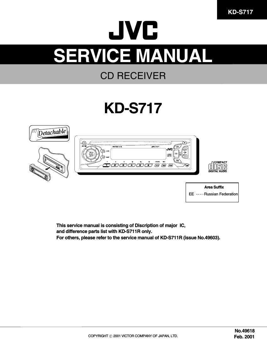
Jvc KDS 717 Service Manual

This is the 34 pages manual for Jvc KDS 717 Service Manual.
Read or download the pdf for free. If you want to contribute, please mail your pdfs to info@audioservicemanuals.com.

Page: 1 / 34
left right
Jvc KDS 717 Service Manual

Extracted text from Jvc KDS 717 Service Manual (Ocr-read)


Page 1

UPD178078GF-544 (IC701) : System CPU 1.Pin la yout 80 ~ 51 1 ~ 30 50 ~ 31 81 ~ 100 Pin NO . 1 2 3 4 5 6,7 8 9 10 11 12 13 14 15 16 17 18 19 20 21 22 23 24 25 26 27 28 29 30,31 32 33 34 35 36 37 38 39 40 41 42 43 44 45 - I I O O - I O O - O O O - O I I I I I I I I I I - I I - - - - - - I - I - - I - I - NC BUSINT BUSSI BUSSO JB US-SCK NC I2CD AI I2CD AO I2CCLK NC LCDD A LCDSCK BUSI/O NC LCDCE SW2 SW3 SW4 RSTSW ENC1 ENC2 KEY0 KEY1 KEY2 LEVEL AVDD SM SQ NC AVSS REGCPU VDD REGOSC X2 X1 GND0 SD/ST GND2 NC IFC VDDPLL OSC NC I/O Symbol FUNCTION Non connection JVC b us comm unication line JVC b us comm unication line JVC b us comm unication line JVC b us comm unication line Non connection Ser ial data input Ser ial data output Ser ial cloc k output Non connection LCD dr iver ser ial data output LCD dr iver ser ial cloc k output JVC b us output select Non connection LCD dr iver comm unication line CD mech s witch CD mech s witch CD mech s witch Traverse mech rest s witch Encoder input Encoder input Key input Key input Key input Audio le vel input Power supply Signal le vel meter input Signal quality input Non connection Connect to GND Connect to GND with capacitor Power supply Connect to GND with capacitor System cloc k System cloc k Connect to GND Station detector & Stereo indicator Connect to GND Non connection IF count input --- FM,AM osc input Non connection 2.Pin function (1/2) Description of major IC

Page 2

Pin NO. 46 47 48 49 50 51 52 53 54 55 56 57 58 59 60 61~68 69 70 71 72 73 74 75 76 77 78 79 80 81 82 83 84 85 86 87 88 89~98 99 100- O O - I I I - O O O O - - - - O O O O I/O I/O I/O I/O O I I I I - O O O O I - - - - GNDPLL AMEQ FMEQ IC(VPP) RESET SW1 REMOCON NC TEL_MUTE POWER CDON MUTE STAGE 1 BUZZER STAGE 2 NC LM0 LM1 BUCK CCE BUS0 BUS1 BUS2 BUS3 RST PS1 PS2 DETACH RDSSCK GND1 MONO SEEK/STOP FM/AM AFCK RDSDATA PLLMONITOR NC VDDPORT GNDPORTI/O Symbol FUNCTION --- PLL error output for AM PLL error output for FM Setting to write for flash System reset CD mech switch Remocon input Non connection TEL mute output Power control CD power control Mute control --- Non connection --- Non connection CD mech driver control CD mech driver control CD LSI communication line CD LSI communication line CD LSI communication line CD LSI communication line CD LSI communication line CD LSI communication line CD LSI communication line ACC detection input Memory detection Detach detection Clock input for RDS Connect to GND Mono by force Switching SEEK & STOP Band switch AFcheck output RDS data input Non connection Non connection Vdd Connect to GND 2.Pin function (2/2)