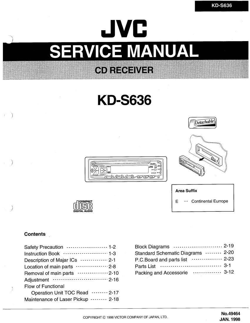
Jvc KDS 636 Service Manual

This is the 60 pages manual for Jvc KDS 636 Service Manual.
Read or download the pdf for free. If you want to contribute, please mail your pdfs to info@audioservicemanuals.com.

Page: 1 / 60
left right
Jvc KDS 636 Service Manual

Extracted text from Jvc KDS 636 Service Manual (Ocr-read)


Page 1

KD-3636

JVB
SERVICE MANUAL

\ /

Area Suffix
MW E Continental Eurrope

/ DIGITAL AUDIO
Contents H
Safety Precaution -------------------- 1-2 Block Diagrams ------------------------ 2-19
Instruction Book ---------------------- 1-3 Standard Schematic Diagrams -------- 2-20
Description of Majar ICs -------------- 2-1 P.C.Board and parts list --------------- 2-23
Location of main parts ---------------- 2-8 Parts List ------------------------------ 3-1
Removal of main parts --------------- 2-10 Packing and Accessorie -------------- 3-12
Adjustment --------------------------- 2-16

\ Flow of Functional

/ Operation Unit TOC Read -------- 2-17
Maintenance of Laser Pickup -------- 2-18

No.49464

COPYRIGHT © 1998 VICTOR COMPANY OF JAPAN, LTD.
JAN. 1998

Page 2

KD-SGBG

1-2

Safety Precaution

A CAUTION Burrs formed during molding may be left over on some parts of the chassis. Therefore,
pay attention to such burrs when preforming repairs of this system.

A cAu110N Please use enough caution to avoid direct exposure to the beam or touch it in case of
an adjustment or operation check.

Page 26

KD-8636

Bracket

Front Bracket Flexible wire

[CD Mechanism Section ]

I Removing the CD mechanism control

G

Fig.10

CD mechanism
control board

P.C.board Be" .9.

1.Remove the CD mechanism assembly
(See "Removing the CD mechanism assembly").

2.Remove the three springs @ and (E from behind the
CD mechanism assembly(See Fig.10).

3.Disconnect the flexible wire connected to the
connector on the CD mechanism control P.C.board
(See Fig.10).

4.Remove the one screw ® retaining the CD mecha-
nism control P.C.board(See Fig. 11).

5. After disengaging the engagement between the
notch section © and trame,remove the CD mecha-
nism Control P.C .board successively from CD through
to © in the arrow direction as shown in Fig. 11.

CAUTION:Whenever the flexible wire is disconnected,
be sure to remove the soldering in advance
as shown in Fig.12. OthenNise ,the CD
mechanism assembly can possibly be
damaged.

6.Remove the two screws CD retaining the front bracket for

fixing the CD mechanism control P. C. board(See Fig.10 or 13).

CAUTION:Remove the front bracket from the frame while
expanding both sides of the frame as shown in
Fig.14

2-12

Loading motor

Fig.11

Pick up Flexible wire

\
_- Soldering

Fig.12

D

CD mechanism
control board