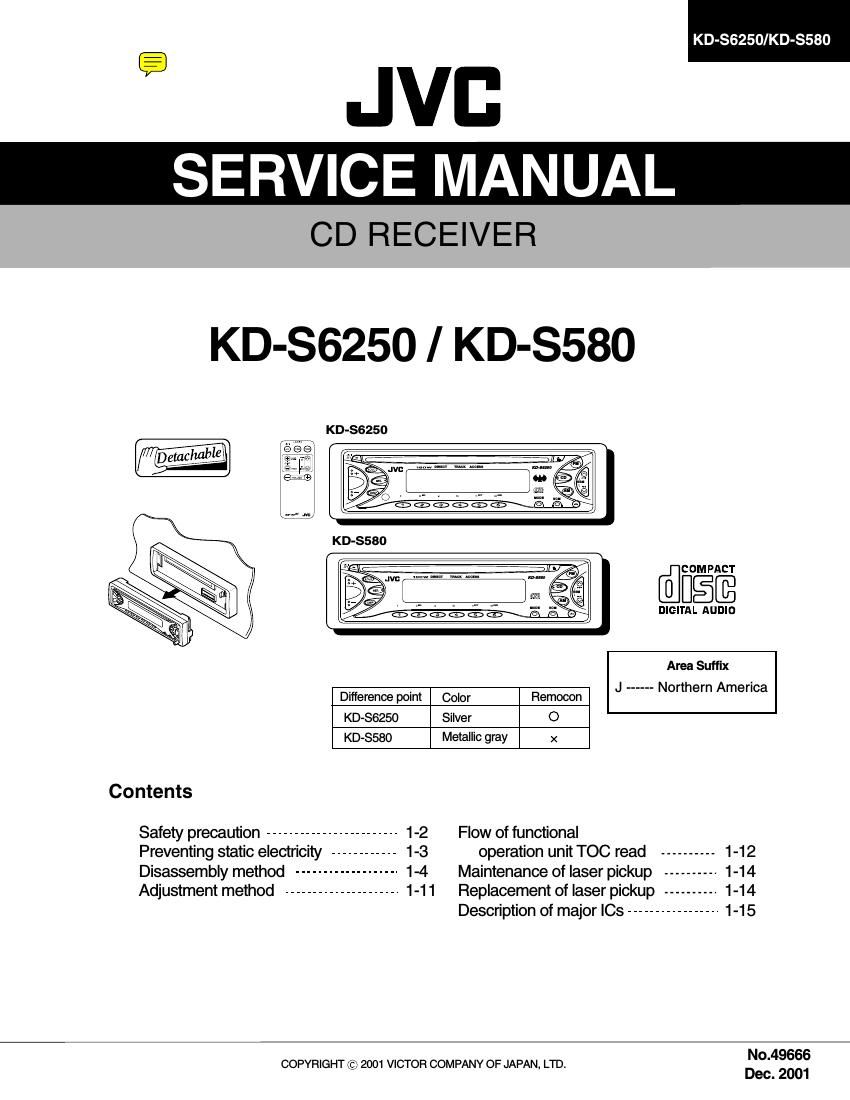
Jvc KDS 6250 Service Manual

This is the 37 pages manual for Jvc KDS 6250 Service Manual.
Read or download the pdf for free. If you want to contribute, please mail your pdfs to info@audioservicemanuals.com.

Page: 1 / 37
left right
Jvc KDS 6250 Service Manual

Extracted text from Jvc KDS 6250 Service Manual (Ocr-read)


Page 1

CD RECEIVER

KD-86250/KD-S580

KD-86250/ KD-S580

KD-SGZSO

@figfi
DIGITAL AUDIO
Area Suffix
Difference point Color Remocon J ------ Northern America
KD-sszso Silver 0
KD-SS8O Metallic gray x
Contents
Safety precaution ------------------------ 1-2 Flow of functional
Preventing static electricity -- - 1-3 operation unit TOC read -------- 1-12
Disassembly method ---------- 1-4 Maintenance of laser pickup 1-14
Adjustment method --------------------- 1-11 Replacement of laser pickup 1-14
Description of major ICs --------------- 1-15
No.49666

COPYRIGHT © 2001 VICTOR COMPANY OF JAPAN, LTD.

Dec. 2001

Page 2

KD-86250/KD-8580

Disassembly method /
§$ \

./ \

I Removing the front panel assembly
(See Fig.1)

1. Press the eject button in the lower right part of the
front panel. Remove the front panel assembly from
the body.

Front panel assembly

Eject button

Fig.1

Tab a

l Removing the front chassis assembly
(See Fig.2 and 3)

- Prior to performing the following procedure, remove
the front panel assembly.

1. Release the four joint tabs a on both sides of the
front chassis assembly and remove the front chassis
assembly toward the front.

Front chassis assembly
Fig.2

Heat sink Tab a

II
/J

Tab a Front chassis
assembly

Fig.3

Page 12

KD-SGZSO/KD-SSBO

Maintenance of laser pickup

(1) Cleaning the pick up lens
Before you replace the pick up, please try to
clean the lens with a alcohol soaked cotton
swab.

(2) Life of the laser diode
When the life of the laser diode has expired,
the following symptoms will appear.
(1) The level of RF output (EFM outputampli
tude of eye pattern) will be low.

ls RF output
1.0: 0.35Vp-p?

Replace it.

O.K

(3) Semi-fixed resistor on the APC PC board
The semi-fixed resistor on the APC printed
circuit board which is attached to the pickup
is used to adjust the laser power.Since this
adjustment should be performed to match the
characteristics of the whole optical block,
do not touch the semi-fixed resistor.

If the laser power is lower than the specified
value,the laser diode is almost worn out, and

the laser pickup should be replaced.

if the semi-fixed resistor is adjusted while

the pickup is functioning normally,the laser

pickup may be damaged due to excessive current.

1-14

Replacement of laser pickup

Turn off the power switch and,disconnect the
power cord from the ac outlet.

Y

Replace the pickup with a normal one.(Refer
to Pickup Removal" on the previous page)

V

Plug the power cord in,and turn the power on.
At this time,check that the laser emits for
about 3seconds and the objective lens moves
up and down.

Note: Do not observe the laser beam directly.

Y
Play a disc.

<-
v

Check the eye-pattern at TP1.

V
Finish.

Page 30

I Parts list (CD mechanism)

KD-S6250/KD-8580

Black No. MBMM

A Item Parts number Parts name O'ty Description Area
71 64180403T DET SWITCH 2 ESE22MH3
72 68150232T CONNECTOR 1 TKC-W26X-C1
79 30311105T SOPPORT PLATE 1
80 30311138T GR MT BLK(N) 1
81 30311109T LDG GEAR (2) 1
82 30311110T LDG GEAR (3) 1
84 30311112T LDG GEAR (5) 1
86 30311136T LDG ROLLER 2
88 30311118T L.P SPRING (L) 1
89 30311119T L.P SPRING (R) 1
90 30311123T SW PCB 1
91 30311124T SW ACTUATOR 1
92 30311129T LDG BELT 1
93 30311140T FRONT BRKT (J) 1
100 9C0620503T C B TAP SCREW 2 M2X5
101 9C2020401T C SCREW TS.G 5 M2X4
102 9C4320403T C B TAP SCREW 4 M2X4
103 9C0117223T SCREW 2 M1.7X2.2
104 9C0917703T C TAP SCREW S3 1 M1 .7X7
105 9C0320201T C TAP SCREW S3 1 M2X2
106 9C4920013T C TAP SCREW SS 2 M2X10
107 9C4920603T C TAP SCREW B3 4 M2X6
108 9P0220031T TAMS SCREW 2 M2X3
109 9C0314203T C TAP SCREW 1 M1 .4X2
110 9C0420253 C TAP SCREW 1 M2X2.5
113 9W0330276 NW BLUE 2 2.9X5X0.3
116 9W0725030T LUMILAR W 1 2.3X9.8X0.25
117 9W0640030T WASHER 1 1.4X3.2X0.4
130 303105310T FEED MO ASSY 1
131 303105311T SPINDLE MO ASSY 1
132 303105312T FEED SCREW ASSY 1
133 303111301T LDG MOTOR ASSY 1
134 303111302T RDG RLR SFT ASY 1
135 303105502T T.T.BASE ASSY 1

3-7