Jvc KDLX 30 Service Manual

This is the 94 pages manual for Jvc KDLX 30 Service Manual.
Read or download the pdf for free. If you want to contribute, please mail your pdfs to info@audioservicemanuals.com.

Page: 1 / 94
left right
Jvc KDLX 30 Service Manual

Extracted text from Jvc KDLX 30 Service Manual (Ocr-read)


Page 1

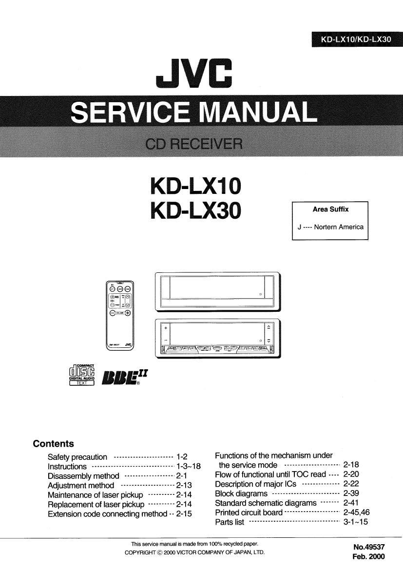
KD~1LX1OIKD ~LX30

JVI:
SERV'CE MANUAL.

KD-LX1 O
KD- Lx3o Area Suffix

J ---- Nortern America


we ~99? 9,9HEIHEA - V?
0 [E III
nun-unit: BB l®
Contents
Safety precaution ---------------------- 1-2 Functions of the mechanism under
Instructions ---------------------- 1-3~18 the service mode --------------------- 2-18
Disassembly method -------------- 2-1 Flow of functional until TOC read 2-20
Adjustment method -------------- 2-13 Description of major ICs -------------- 2-22
Maintenance of laser pickup ---------- 2-14 Block diagrams ------------------------- 2-39
Replacement of laser pickup ---------- 2-14 Standard schematic diagrams ------- 2-41
Extension code connecting method -- 2-15 Printed circuit board --------------------- 2-45,46
Parts list ---------------------------------- 3-1 ~15
This service manual is made from 100% recycled paper. No.49537

COPYFllGHT © 2000 VICTOR COMPANY OF JAPAN, LTD.
Feb. 2000

Page 2

KD-LX10/KD-LX30

Safety precaution

A CAUTION Burrs formed during molding may be left over on some parts of the chassis. Therefore,
pay attention to such burrs in the case of preforming repair of this system.

A CAUTION Please use enough caution not to see the beam directly or touch it in case of an
adjustment or operation check.

1-2

Page 10

KD-LX10/KD-LX30

[ Assigning names to the sources ]

Select the charactersetyou wantwhile is flashing.
Each time you press the button the charader Set Changes as toliows

flm luter(H)~> Small team-3t "l

uumtms and symhols 12!) + «4

You can assign names to shliun lrequenctes CD8 and the external component unwanted to
the LiNE iN Diugstlar assigning 3 Mental iiwii appear on the display when you saiect me
source

ENGUSH
ENGLiSH

ms at
up lo 12 chamcters (up to

bolh FM and
' to characters to Au 4
External lo12 characters
' ml t "mi. (lstiflll ii liaillt m u <7) Amt

Select a character
About the ewilable charaders, see page 31

Move the cursor to the next (or previous) character
position

Seiect a source you want lo aSSIgn a name to.

Repeat steps 3to 5 until you finish inputting the name.

Press and hold SEL (Select) for more than 2 7
seconds while pressing DISP Press the button while the last selected character is
__.# flashing
wn n ous i | Stilton .
"19sz a: in: gum l; m input name is stored in memory.
FflL-J To erase the input characters
insarl spaces using the same pmcfidure described above.
W i tilt CD "
as 5.32122 '3 l 6
[II 3m:
When you select me
i i l
gamma u ll- INE INPUT
mm x .' aflfi

cwiiniim tn lhs iisxi page
30

REMOTE OPERATIONS


Remote sensor


Available charcuers

(2 int I $ E, Belore using the remate commller

"P ' m g j - Aim the remotecomrulierdiractlyattheremotesensor
A B C D E F G H I J -1-, % ggxgenmain iinit Make sure there is no obstacte in
K L M N O P Q R S - Do not expose the remote sensor to strong light (direct

sunlight or artiticiat lighting).

UVWXYZW

Smnl an."
d . , finstalling the battery J

When the controllabte range or ellectweness 01 9 remole controller decreases replace
k I mnopqr 5 thebattery

uvwxyzwe l

1. Emma [III batt-ry hotdar.

Mumbm and Iymbol: mu me) it Push out in the direclton indicated by the armw
I) using a bait paint pen or a stmilartoat,
0 1 2 3 4 5 5 7 8 9 2) 2) Removelhe biliary haltlar
! , at $ % s. ' ( ) ~

Lllmum coin battery

1, Final the hlltory.
Slide the buttery into the hoidarwilh me ¢ Side raung
upwards so thntttie battery isltxad in the nuiaiir

+
|
A
II
V
i
2
5
g

cnznzsi

@ _ space

J. Rllurn the tummy hold".
(Midst Insarl spin the battary holder pushing it until you
tiear a cttokiiig wund
Not":
~ W u n /1! In It) Mulglltllwmtlrl rim/trait. NAMI.
Mat-u: -( gfld/lmmm Im/orr' unizdnmotl ; U) I / w I I1
- mel u ' rm anti-mm ,uiiiiuiiuiu Hmllrwt m ' i ililit'lu mum Inc ,
"um um illm lief/mun ml I/IU diultui 1") 01st m l 1); In [his unit, WARN'NG'

II uplutlnrm m mum. «in mututu.

Slur?l/wltrllmflt'nmuplut min-1 iiiiamitiiiuwmv 1i

l/u(lullltltler/i/rllll warm l/rt- 1mm lirlltittli'u/t iiiuiiuiudmmr

Humilitflhumd mun IIIJUJXl'illIIIt'nflicltI/litliuI/vr urdirpii.u».iriiiii/iiiv

rimiiu um 0/th mum flmt «mam Ira/mitt in gn'fl .Wuui (w. t iii-trim u (in'

nu ml/ Inn-c rim Ital/win wry/i (ll/it" maul/it mmmui:

imiu m min tum lln lml/twct H) uiiwimu-ui mitt "131!" Hflfk,

W/n'nllllviwmglmtl lraw't'ttgl/lclmllt m uranium/wuirrllrmtluu Murmur ,iiiiiui-iuw
[hr Mllrrit': to Kim try hull mm m um a Hm.

1)., mi puke l/tu liar/c .i u rm imimm .iruiiiiiurumii

[lintgl/Htlmn iuumriu umitumuiicamwi truttumim ti 1m

at 32

Page 29

lRemoving the loading motor
(See Fig.3 to 5)

- Prior to performing the following procedure, remove
the CD mechanism control board.

1. Remove the two springs f attaching the CD mechanism
assy and the front bracket.

2. Remove the two screws B and the front bracket
while pulling the flame outward.

3. Remove the belt and the screw C from the loading
motor.

lRemoving the CD mechanism assy
(See Fig.1, 6 to 9)

- Prior to performing the following procedure, remove
the CD mechanism control PWB and the front
bracket (loading motor).

1. Remove the three screws D and the damper bracket.

2. Raise the both sides fix arms and move the fix plates
in the direction of the arrow to place the four shafts g
as shown in Fig.8 and 9.

3. Remove the CD mechanism assy and the two
springs h attaching the flame.

4. Remove the two screws E and both sides rear
damper brackets from the dampers. Detach the CD
mechanism assy from the left side to the right side.

ATTENTION: The CD mechanism assy can be
removed if only the rear damper
bracket on the left side is removed.

KD-LX10/KD-LX30

Loading motor

Rear damper bracket
Fix plate (L) E Fix arm (L)

m

->_ * f
/

g Damper

Fig.8

E Flear damper bracket

Fix arm (R)

2~11