Jvc KDLX 110 R Service Manual

This is the 33 pages manual for Jvc KDLX 110 R Service Manual.
Read or download the pdf for free. If you want to contribute, please mail your pdfs to info@audioservicemanuals.com.

Page: 1 / 33
left right
Jvc KDLX 110 R Service Manual

Extracted text from Jvc KDLX 110 R Service Manual (Ocr-read)


Page 1

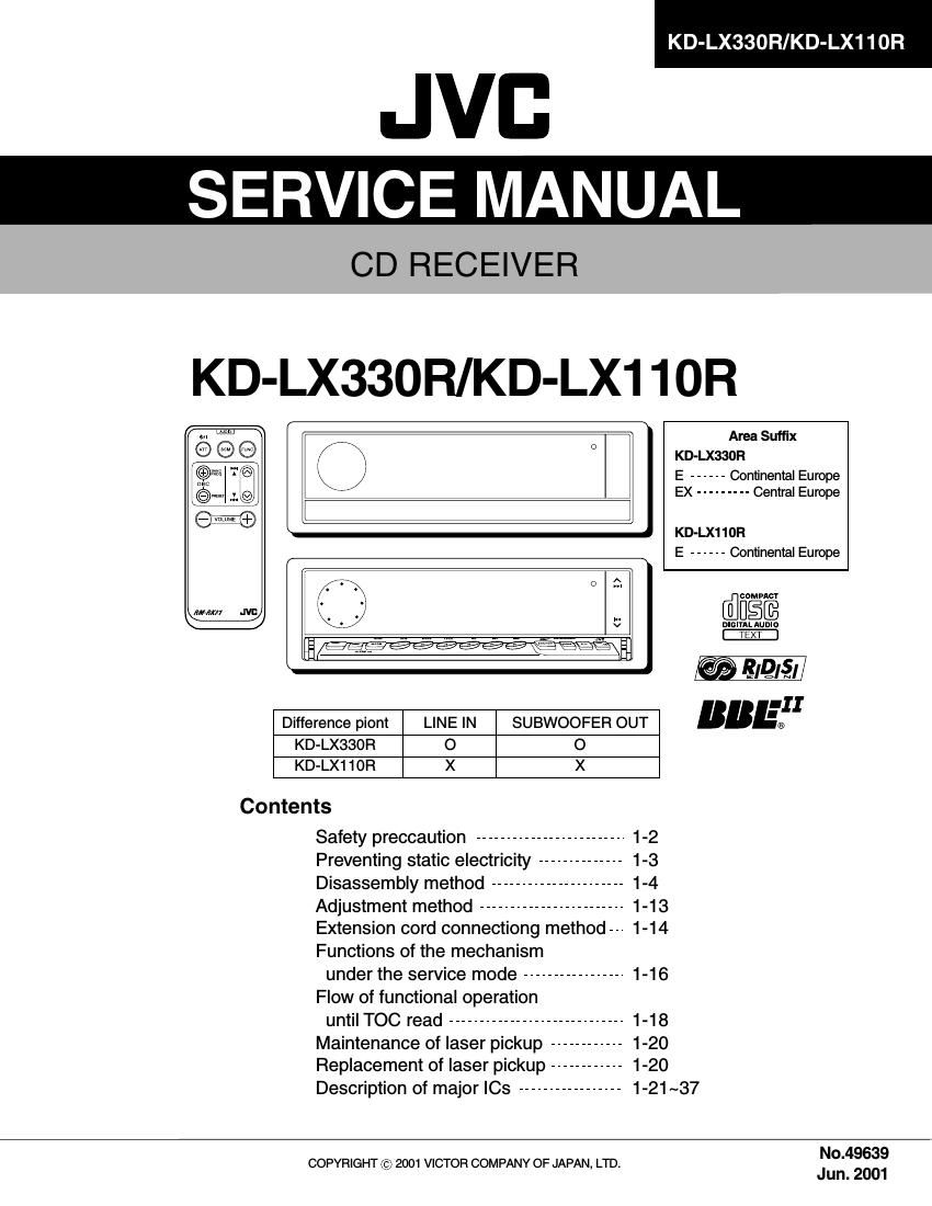
KD-LX330R/KD-LX110R

JVB
SERVICE MANUAL

CD RECEIVER

KD-LX33OR/KD-LX1 10R

Area Suffix
KD-LX330R
E ------ Continental Europe
EX --------- Central Europe
KD-LX11OR
E ------ Continental Europe
umnaam
5f}? 8/9/51
III
Difference piont LINE IN SUBWOOFER OUT "B .6}
KD-LXSSOR o o
KD-LX110R X X
Contents

Safety preccaution ------------------------- 1-2

Preventing static electricity -------------- 1-3

Disassembly method ---------------------- 1-4

Adjustment method ------------------------ 1-13

Extension cord connectiong method-- 1-14

Functions of the mechanism

under the service mode ----------------- 1-16
Flow of functional operation
until TOC read ----------------------------- 1-18

Maintenance of laser pickup ------------ 1-20

Replacement of laser pickup ------------ 1-20

Description of major ICs ----------------- 1-21 ~37

No.49639

COPYRIGHT 6) 2001 VICTOR COMPANY OF JAPAN, LTD.
* Jun. 2001

Page 2

Description of major le

I FAN8037 (IC661) : CD driver
1. Pin layout & Block diagram

48 47 4e 45 44 43

42 41 40 39 38 37

:J

KD-LX330R/KD-LX11OR

36

2 4 . : , 35
3 4.: 34
*jjéflm- 4M3 +

4 : - 33

5 + W : 32

6 «I «I: 31

:\Q I

7 30

8 51 131 : 29

9 28

10 2

11 iv 03" : 26

12 T-S-D imi: 25

13 14 15 16 17 18 19 20 21 22 23 24
2. Pin function

519 Symbol I/O Function m? Symbol l/O Function
1 |N2+ l CH2 op-amp input(+) 25 DO7+ 0 CH7 drive output(+)
2 |N2- l CH2 op-amp input(-) 26 D06- 0 CH6 drive output(-)
3 OUT2 0 CH2 op-amp output 27 DO6+ 0 CH6 drive output(+)
4 |N3+ l CH3 op-amp input(+) 28 PGND2 - Power ground2
5 |N3- l Ch3 op-amp input(-) 29 005- 0 CH5 drive output(-)
6 OUT3 0 CH3 op-amp output 30 D05+ 0 CH5 drive output(+)
7 |N4+ l CH4 op-amp input(+) 31 004- 0 CH4 drive output(-)
8 |N4- l CH4 op-amp input(-) 32 DO4+ 0 CH4 drive output(+)
9 OUT4 0 CH4 op-amp output(+) 33 003- 0 CH3 drive output(-)
10 CTL1 l CH5 motor speed control 34 D03+ 0 CH3 drive output(+)
11 FWD1 | CH5 forward input 35 PGND1 - Power ground1
12 REV1 l CH5 reverse input 36 002- 0 CH2 drive output(-)
13 CTL2 | CH6 motor speed control 37 D02+ 0 CH2 drive output(+)
14 FWD2 l CH6 forward input 38 001- 0 CH1 drive output(-)
15 REV2 | CH6 reverse input 39 DO1+ 0 CH1 drive output(+)
16 SGND - Signal ground 40 PVCC1 - Power supply voltage
17 FWD3 I CH7 forward input 41 REGOX l Regulator feedback input
18 REVS l CH7 reverse input 42 REGX O Regulator output
19 CTL3 I CH7 motor speed control 43 RESX l Regulator reset input
20 SB I Stand by 44 VREF l Bias voltage input
21 PS I Power save 45 SVCC - Signal supply voltage
22 MUTE | All mute 46 |N1+ l CH1 op-amp input(+)
23 PVCC2 - Power supply voltage 47 |N1- l CH1 op-amp input(-)
24 D07- 0 CH7 drive output(-) 48 OUT1 0 CH1 op-amp output

1-21