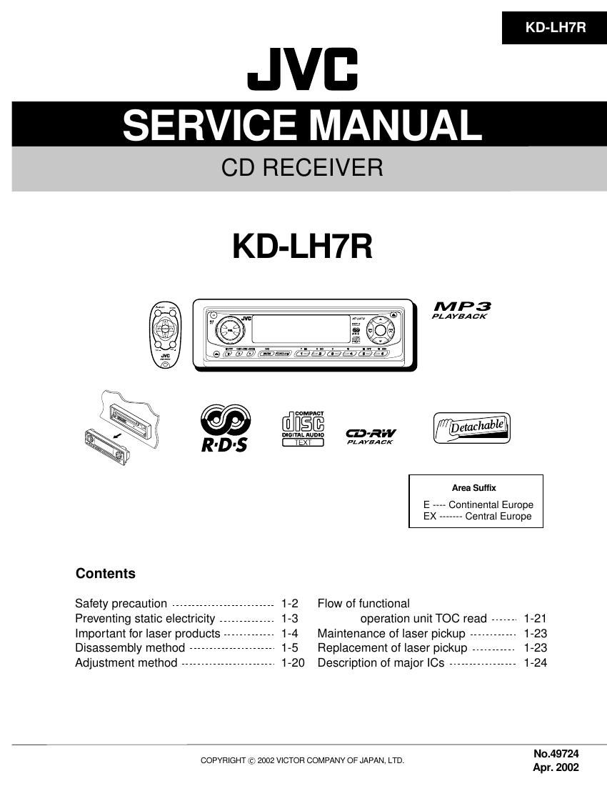
Jvc KDLH 7 R Service Manual

This is the 73 pages manual for Jvc KDLH 7 R Service Manual.
Read or download the pdf for free. If you want to contribute, please mail your pdfs to info@audioservicemanuals.com.

Page: 1 / 73
left right
Jvc KDLH 7 R Service Manual

Extracted text from Jvc KDLH 7 R Service Manual (Ocr-read)


Page 1

JVB

SERVICE MANUAL

CD RECEIVER

KD-LH7R

MP3

FLA YEA CK

@ @ COMPACT
D-IEIQEJQ GJ-RW

R. D .5 _E>

Area Suffix
E Continental Europe
EX ------- Central Europe
Contents
Safety precaution -------------------------- 1-2 Flow of functional
Preventing static electricity .............. 1-3 operation unit Too read ...... 1-21
important for laser products ------------- 1-4 Maintenance of laser pickup ------------ 1-23
Disassembly method --------------------- 1-5 Replacement of laser pickup ----------- 1-23
Adjustment method ------------------------ 1-20 Description of major ICs ----------------- 1-24
, No.49724
COPYRIGHT (c) 2002 VICTOR COMPANY OF JAPAN, LTD.

Apr. 2002

Page 2

KD-LH7R

Safety precaution

A CAUTION Burrs formed during molding may be left over on some parts of the chassis. Therefore,
pay attention to such burrs in the case of preforming repair of this system.

A CAUTION Please use enough caution not to see the beam directly or touch it in case of an
adjustment or operation check.

1-2

Page 36

KD-LH7R

I PCM1716E-X (IC571) : D/A converter

1. Pin layout

15
flflflflflflflflflflflflflfl

O

UUULILIUUUULILIUUU

.4 CE
1 14 g g g g
o C! o (D
2. Block diagram > 4 >
BCK Serial LOW, ass VoutL
LBCK Input MmHeve, a DAG Filtper x;
I/F 8X Oversampllng . iEXTL
DATA Digital Filter Denarsgma lil- Lowrpass VomR
with M°d'a1°' a mo Filter
ML/S fFunctlon Controller K*iEXTFI
MC/DM1 Mode
MEDMO Control L AFRO
MUTE
m T-{ Crystal OSC H | Power Supply |
l
_ , XTI XTO CLKO Vcct AGNDI Vcc DGND
3. Pin function
{112 Symbol l/O Function
1 LRCK I LRCK clock input
2 DATA l Serial audio data input
3 BCK I Bit clock input for serial audio data
4 CLKO O Buffered output of system clock
5 XTI I Oscillator input / External clock input
6 XTO O Oscillator output
7 DGND » Digital ground
8 VDD » Digital power +5V
9 VDD2R » Analog power +5V
10 AGND2R » Analog ground
11 EXTR O Rch common pin of analog output amp
12 NC » Non connection
13 VOUTR O Rch analog voltage output of audio signal
14 AGND1 » Analog ground
15 Vcc1 » Analog power +5V
16 VOUTL O Lch analog voltage output of audio signal
17 NC » Non connection
18 EXTL O Lch common pin of analog output amp
19 AGND2L » Analog ground
20 Vcc2L » Analog power +5V
21 ZERO 0 Zero data flag
22 RST l Reset
23 CS/IWO I Chip select/ Input format selection
24 MODE I Mode control select
25 MUTE I Mute control
26 MD/DMO I Mode control, Data / De-emphasis selection 1
27 MC/DM1 I Mode control, BCK/ De»emphasis selection 2
28 ML/IIS I Mode control, WDCK/ Input format selection

1-36