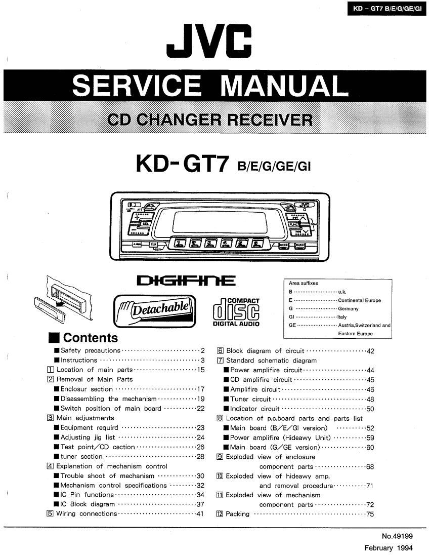
Jvc KDGT 7 Service Manual

This is the 94 pages manual for Jvc KDGT 7 Service Manual.
Read or download the pdf for free. If you want to contribute, please mail your pdfs to info@audioservicemanuals.com.

Page: 1 / 94
left right
Jvc KDGT 7 Service Manual

Extracted text from Jvc KDGT 7 Service Manual (Ocr-read)


Page 1

KD V GT7 B/E/G/GE/Gl

JVB

SERV CE

MANUAL

KD' GT7 B/E/G/GE/Gl

@-

I Contents


lSafety precautions -------------------------- 2

.Instructions ................................. 3
Location of main parts --------------------- 15
Removal of Main Parts

IEnclosur section ........................... 17

IDisassembling the mechanism'-'-

ISwitch position of main board ----------- 22
Main adjustments

IEquipment requird .........................

IAdjusting jig list --------------

ITest point/ CD cection ----------------- 26

Ituner section .............................. 28
Explanation of mechanism control

ITrouble shoot of mechanism ------------- 30

IMechanism control specifications --------- 32

IIC Pin functions --------------------------- 34

IlC Block diagram -------------------------- 37
Wiring connections -------------------------- 41

DlGl-F-III-E

Areasuflixes
B u uk.
COMPACT E .. ~ Continental Europe
@US@ G ~--Germany
Gl-m- ----- Italy
DIGITAL AUDIO GE Austria5witzerland and
Eastern Europe
5] Block diagram of circuit ------------------- 42
[fl Standard schematic diagram
IPower amplifire circuit -------------------- 44
ICD amplifire circuitm ------ 45
IAmplifire circuit ----------- 46
ITuner circuit -------------- 48
Ilndicator circuit ---------------------------- 50
{E Location of p.c.board parts and parts list
IMain board (B/E/Gl version) ---------- 52
IPower amplifire (Hideawy Unit) ---------- 59
IMain board (G/GE version) -------------- 60
IE! Exploded view of enclosure
component parts ................. 68
fl] Exploded visw'cf hideawy amp.
and removal procedure ----------- 71
E] Exploded view of mechanism
component parts ----------------- 72
Packing ..................................... 75

February 1994

Page 2

KD - GT7 B/E/G/GE/Gl

I Safety Precautions

Important for Laser Products

1. CLASS 1 LASER PRODUCT

2. DANGER: Invisible laser radioation when open and in-
terlock failed or defeated. Avoid direct exposure to beam.

3 CAUTION: Do not open the bottom cover. There are no
user serviceable parts inside the unit; leave all servicing
to qualified service personnel.

4. CAUTION: The compact disc player uses invisible laser

radiation and is equipped with safety switches which pre»

vent emission of radiation when unloading cartridge and

the safety interlocks have failed or are defeated. it is

dangerous to defeat the safety switches.

CAUTION: Use of controls of adjustments or performance

of procedures other than those specified herein may

result in hazardous radioation exposure.

9

IDENTIFICATION LABEL AND CERTIFICATION
LABEL

ADVERSEL: Usvnllg laserstréling ved arming. nar sik-
kerhedsafbrvdere er ude af funktion. Undge
udsattelse for strafing.

VAROITUS: Varmuuskytkimen oliessa pois pfialtikun
Iaite avataan, siellé kehittyy nfikymézébté lasersfitails.
Ala pane itseési séteiiyn altiiksi.

VARNING: Osvniig laserstAining uppstér vid kom-
ponantens opening n5! sékerhetsbrytaren fir
IrAnsiagon.

ADVARSEL: Usynling lasersualing ved apnlng nar sik-
kerhetsbryteren er ude at funktion Unngé utsettelse
for strafing.

Bottom panel of the main unit

ADVARSEL-Der vii udsirales DANGER-Invismie laser

CLASSi


osynlig laserpestrallng nar
aoperaiei ébnes og alias~
ningsmekanismen irigores
UNDGA AT BLIVE UDSET
FOR LASERBESTRALING.

radiation when open and
inieriock deleated.
AVOID DIRECT EX-
POSURE TO BEAM.


LASER PRODUCT

Obs:
Apparsten lnnehaller laser-

2 (No.49199)

Page 3

Content of Instruction

Features..... 3
Specification 3
Important information .. ................................. 3
Precautions 4
Installation . .. 4
Playing compact disc .................................... 5
Location of controls ................... . ........ 7
Concerning compact disc and magazine .. 9
Digital clock display ...................................... 14
SSR ............ . 14

Maintenance

1 SPECIFICATIONS

CD CHANGER [AUDIO AMPLIFIER SECTION

Type: Compact disc player

Signal Detection System: Non- contact optical pickup
(semiconductor laser)

Number of Channels: 2 channels (stereo)

Frequency Response: 5 to 20,000 Hz

Dynamic Range: 95 dB

Signal-to-Noise Ratio: 98 dB

Wow & Flutter: Less than measurable limit

Output Level: 1 5 V/20 kn load (Full scale)

Output Impedance: 1 k9
Maximum Power Output: (Front) 25 W per channel
(Rear) 25 W per channel

Continuous Power Output (RMS): (Front) 12 W per
channel into 4 Q, 40 to 20,000 Hz at no more than
0.8% total harmonic distortion (Rear) 12 W per
channel into 4 Q, 40 to 20,000 HZ at no more than
0.8% total harmonic distortion.

Load Impedance: 4 n (4 to 8 Q allowance)

Tone Control Range
Bass: :10 dB at 100 Hz
Treble: :10 dB at 10 kHz

Frequency Response: 40 to 20,000 Hz

Signal-to-Noise Ratio: 70 dB

RADIO SECTION
Frequency Range
FM: 87.5 to 108.0 MHZ
AM: (MW) 522 to 1,620 kHz
(LW) 144 to 279 kHz
[FM Tuner]
Usable Sensitivity: 12.1 dBi ( 1.1 pV/75 Q)
50 dB Quieting Sensitivity: 16.8 (181 (1.8 uV/75 [1)
Alternate Channel Selectivity: (400 kHz): 65 dB
Frequency Response: 40 to 15,000 Hz
Stereo Separation: 30 dB
Capture Ratio: 1.5 dB
[MW Tuner]
Sensitivity: 20 v
Selectivity: 35 dB
[LW Tuner]
Sensitivity: 50 uV

GENERAL
Power Requirement
Operating Voltage: DC 14.4 volts (11 to 16 volts
allowance)
Grounding System: Negative ground
Dimensions (W x H x D)
Installation Size: 182 x 52 x 165 mm (7-3/16" x
2-1/16" x 6-1/2")
Panel Size: 190 X 58 x 20 mm (7-1/2'I X 2-5116" x
1 3/1 6")
Amplifier unit: 178 x 25 x 170 mm (7-1/8" x 1" X
6-3/4")
Gross Weight: 3.6 kg (8 lbs)

USABLE MAGAZINES
3-CD Magazine (XG-MSD)

Design and specifications subject to change without
notice.

1 IMPORTANT INFORMATION

KD w GT7 B/E/G/GE/Gl

FEATURES

0 3~Disc Magazine Loading System

I Detachable Control Panel

a Direct Disc Select/Skip Play/Search Play/
Repeat Play/Random Play/Intro Play

0 High Sensitivity Tuner

0 AM/FM Stereo PLL Synthesizer Tuner

I 24~Station Preset Tuning (FM-18, AM
[MW/LW]v6)

o Preset Scan/Scan/Seek/Manual Tuning

0 Strong-station Sequential Memory (SSM)

o Special-preset Station Reserve (SSR)

o SK/DK Traffic Information Reception (G/GE)

o 4-Channel Amplifier System

0 Maximum Power Output of 25 watts per
channel (Front)/25 watts per channel (Rear)

0 Active Hyper-Bass Sound

0 Active-illuminated Operating System (A08)

0 Digital Clock Display

0 Line Output Terminals (Front/Rear)

1. This unit is designed to operate with 12 volts
DC, NEGATIVE ground electrical systems
only.

2. Replace the fuse with one of the specified
rating. If the fuse blows trequently, consult
your JVC "IN-CAR ENTERTAINMENT
dealer.

3. It noise is a problem...

This unit incorporates a noise filter in the
power circuit. However, with some vehicles,
clicking or other unwanted noise may occur. It
this happens, connect the unit's rear ground
terminal to the car's chassis using shorter
and thicker cords, such as copper braiding or
gauge wire. Ii noise still persists, consult your
JVC "IN-CAR ENTERTAINMENT'I dealer.

Antenna Noise

It you can hear static noise when listening to
either AM (MW/LW) or FM, check for loose
antenna connections.

Microcomputer Reset Button

After completing installation and all connections,
press this button (using a ball-point pen, etc.) to
reset the built-in microcomputer. Use this button
only when the power supply is interrupted, such
as after replacing the car's battery, when the
microcomputer does not tunction correctly due to
noise, or when this unit's buttons do not operate
normally.

0 When the message "ERROR 11-16" is shown
in the display, press the Reset button.

- This unit requires several seconds to fully reset
when the Reset button is pressed. Pay
attention as the control panel opens after
resetting the unit.

Microcomputer reset button

(No.49199) a