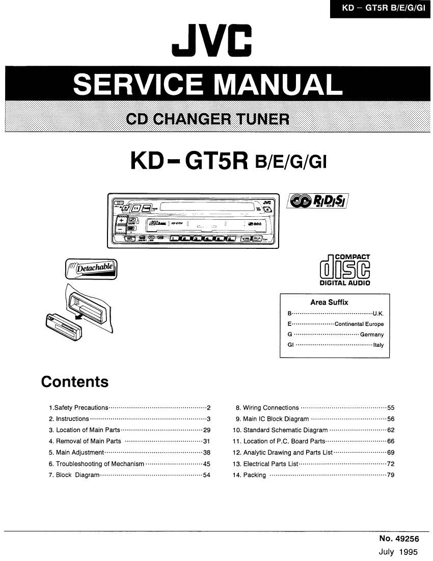
Jvc KDGT 5 R Service Manual

This is the 92 pages manual for Jvc KDGT 5 R Service Manual.
Read or download the pdf for free. If you want to contribute, please mail your pdfs to info@audioservicemanuals.com.

Page: 1 / 92
left right
Jvc KDGT 5 R Service Manual

Extracted text from Jvc KDGT 5 R Service Manual (Ocr-read)


Page 1

KD -- GTSR B/E/G/Gl

.JVB

SERVICE MANUAL

KD- GT5R B/E/G/Gl

/@ 8IQI§I //

COMPACT
0/ [mac

DIGITAL AUDIO
Area Suffix

B .......................................... U.K.

' - Continental Europe

............... Gemany

GI ....................................... "aw

Co ntents

1.33:3, precautions ................................................ 2 3. Wiring Connections ......................................... 55
2_ Instructions ........................................................ 3 9' Main IC Block Diagram ..................................... 56
3. Location of Main Parts ----------- 29 10. Standard Schematic Diagram ------------ 62
4 Removal of Main Parts ----- 31 11. Location of RC. Board Pans -------------- 66
5. Main Adjustment ----------------------------------------------- 38 12. Anaiytic Drawing and Parts List .......................... 59
6. Troubleshooting of Mechanism ----- 45 13. Electrical Parts List ----------- 72


7 Block Diagram --------- 14. Packing

No. 49256
Juiy 1995

Page 2

KD , GTSR B/E/G/Gl l
1. Safety Precautions

Position And Reproduction 0f
Labels

Bottom panel of the main unit

imam fi'HaL'mel'Whe" . , DANGER Invismle laser wmtmg W, Vlflfllflfizownlig lasei~ VAHO:Avmessausuiy
anneaum rieurde aWaeIPWC'Pa ianniicnwrenopenam suammveujtmmnai siniimnqnainennaaei iaimivsunnmaessacei

item mad or warm gramme er nae av aroma om spam fir aimina nahymattomalle
w Aminnirm FXW alluiiktm [Mgéuusat minunim Bahama ei iaseiséiewue Ali man
|:}_,__ T0 BEAM (5:) lelselm smiling (0 slifllen (s saleesem U)

CLASS
LASER

1
PRODUCT


Obs:

Apparaten inneiiéller laserr
komponenl av hegre Iaserklass
an klass l

IMPORTANT FOR LASER
PRODUCTS

Precautions

i. CLASSi LASER PRODUCT

2. DANGER: Invisible laser radiation when
open and interlock failed or defeated. Avoid
direct exposure to beam.

3. CAUTION: Do not open the top cover. There
are no user-sewiceable parts inside. Leave
all servicing to qualified service personnel.

4. CAUTION: This CD changer uses invisible
laser radiation, however, is equipped with
safety switches to prevent radiation emission
when unloading the CD magazine. it is
dangerous to defeat the safety switches.

5. CAUTION: Use of controls, adjustments or
performance of procedures other than those
specified herein may result in hazardous
radiation exposure.

2 (No. 49256)

Page 34

KD ~ GTSFi B/E/G/GI

I Removing the door opener unit
(See Fig. 4-15)

1. Remove the two screws (2) retaining the door opener
unit on the left side of the unit.


Door opener

unit
Fig. 4-15
I Removing the guide plate assembly
(See Fig. 4-16)
Remove the two screws (3) retaining the guide plate ,
Guide late
assembly assemgiy \¥\
A a Pawl (F)
@ 63/ \d/ /
Lever Guide plate l
assembly


Magazine
bracket (1 )

I Removeing the guide plate assembly
(See Fig. 4-16)

1. Engage the magazine bracket (1) and pawl (F) with the
groove on the right side of the guide plate assembly.

2. After hooking the lever provided on the back side of the
guide plate assembly to the front of the stud on the sub
chassis unit and aligning the lever to the screw hole
position, clamp the screw (3).

34 (No. 49255)