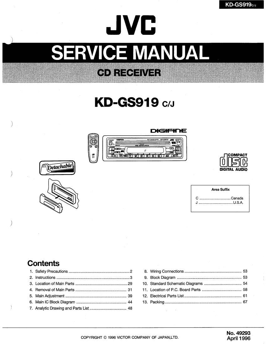
Jvc KDGS 919 Service Manual

This is the 82 pages manual for Jvc KDGS 919 Service Manual.
Read or download the pdf for free. If you want to contribute, please mail your pdfs to info@audioservicemanuals.com.

Page: 1 / 82
left right
Jvc KDGS 919 Service Manual

Extracted text from Jvc KDGS 919 Service Manual (Ocr-read)


Page 1

K G39190/J

JVB
SERV CE MANUAL

itiznm unruly-L-lt-lillzfignfl dlcfloglfi
D DIGITAL AUDIO

Area Suffix

Contents
1 Safety Precautions ........................................................ 2 8. Wiring Connections .................................................... 53
2. Instructions ................. 9. Block Diagram ........................... . 53
3. Location of Main Parts 10. Standard Schematic Diagrams .. . 54
4. Removal of Main Parts 11. Location of RC. Board Parts .................................... 58
5. Main Adjustment ............ 12. Electrical Parts List ..... 61
6. Main IC Block Diagram .. 13. Packing ....................... 67
l 7. Analytic Drawing and Parts List .................................. 48
No. 49293

COPYRIGHT © 1996 VICTOR COMPANY OF JAPAN,LTD. Apr" 1996

Page 2

KD'GSg19C/J

1. Safety precautions

IMPORTANT FOR LASER
PRODUCTS (For U.S.A. only)
Precautions

1. CLASS 1 LASER PRODUCT

2. DANGER: Invisible laser radiation when open
and interlock failed or defeated. Avoid direct
exposure to beam.

3. CAUTION: Do not open the top cover. There
are no user-serviceable parts inside. Leave
all servicing to qualified service personnel.

4. CAUTION: This CD player uses invisible laser
radiation, however, is equipped with safety
switches to prevent radiation emission when
unloading 005. It is dangerous to defeat the
safety switches.

5. CAUTION: Use of controls, adjustments or
performance of procedures other than those
specified herein may result in hazardous
radiation exposure.

Identification And Certification Labels

US JVC CORP. 41 SLATER DRIVE
ELMWOOD PARK. N.J. 07407
MANUFACTURED AT
MADE IN _
Product complies with DHHS Rules 21
CFR Subchapter J in effect at date of
manufacture.

MANUFACTURED

Notes:

1 The date of manufacture.

*2 The ID code of manufacturing plant.
'3 Marking of country origin.

Bottom panel of the main unit

EI

NAME/RATING PLATE

system.

A CAUTION

Burrs formed during molding may be left over on some parts of the chassis.
Therefore, pay attention to such burrs in the case of preforming repair of this

2 (No. 49293)

Page 9

B. 4-Speaker connections when
adding a power amplifier

B. Conexlones de 4 altevoces euando
se lnsiaia un amplificador de

KD-GSQ19c/r

B. Raccordements de 4 haut-parleurs
en aloutant un amplliicateur de

potencle pulssance
Not used
No utilizadu
Non ulilise
Rear/R m WM
FosteriégrlDerecho f-H P°§e"°zqed°
Arrr'are/Drari\_ AmWGflLW
FronlILeft
DelamelD/lzquierdo if 5995f
Maul/Gauche lavoz de anlero
MSW :QHWMW
From/ gilt
Line out DelanierolDereono
Saiida as linear AvanDmr'I
Sonia d9 ir'gne
Power amplifier Hear speaker
Ampliiicador de potencia Aime: poslerior
Amplificaieur d9 puissance :[q Hauwansur arn'ere

c. Line Terminal Connections (Line
out)

Sines this unit has iine-outterminels. an amplifier

and other equipment can be used to upgrade

your car stereo system.

0 With an ampiiiier, connect this unit's line-out
terminals to the amplifiers line-in terminals

1. 2»Ampiiiier oonneclions

G. Gonexlones dei terminal de Iinea
(Sallda de ilnea)

Como esla unidad posee ierminales de salicla

de lines, se puede utilizar un amplificador u otro

equlpamienio para meiorar el sisterna

estereoionioo de su automovii.

0 Con un amplification conecie Iosterminales de
selida de linea de esta unidad can 103
terminales de entrada de Iinea delarnpiiiicador.

1V Conexiones de 2 ampliiicadores

c. Raccordements de homes de Ilgne
(Sortle ilgne)

Comma vetappareila des homes as some Ilgne.

un amplificateurerdaures apparel/speuvenréire

utilises pour améliarer valre chains slérea auto.

0 Aver; un amplilrbaiaur, rewards! [as barnes de

. sortie Iigne do cereppareii aux Domes denlrée
ligne de /anwlificateur.

13

1. Rawardemenrs de deux amplificaleurs

(KD~GSQ19 only) (KDGSS19 exclusivamenie) (KB-65919 uniquemen!)
Llne out (From)
Sande de linea (Delaniero)
Sonia do Ilgne (Al/ant)
_ Power ampiliier :1] I Front speaker
KD-GSQIQ Ampiilicador de pmencia Alravoz dsiantero
Ampiilicaraurdapulseance =(1 Hautflafleuravam
Line out (Rear)
Salida de unea (Posterior) (I
. Power empllller Reer speaker
Sonia 9 9' mm Amplrircauor d9 potencia Altavoz posterior
Ampilllcateurdepulseance =[d Haul-paneuramere

2 single amplifier connections (front or rear)
(KB-65919 only)

2. Conexiones de un solo amplificador
(delantero o lrasero)
(KB-(35919 exclusivamente)

2. Haccordemen! dun seul amplificaieur (a vent
au arriere)
(KO-G8919 uniquemenr)

KD-GSMD

Power ampliiler
Amprrrrcadnr de palencia
Amp/Ificaieur de puissanoa

V"

From or Rear speaker
Altavox delantero o posterior

Heur-parleur avani ou am'ere

M

(No. 49293) 9

Page 12

KD GS9190/J

20

@ Indicators (lor CD section)
LOAD

0

PLAY

Track number
Time

RPT

RND

INT

(KB-68919 only)
EJECT

NO DISC

Q Indicators (tor CD ChangerControl sections)
CD-CH
0
CD
Magazine number (When connecting the XL-
M61800)
Disc number
Track number
RPT
FIND
INT (1, 2) [KD-GSQIQ only)
NT (1 , 2, 8) (When connecting the XL-
M61800) (KB-65919 only)
DOOR (When connecting the XL»M61800)
NO MAG
NO DISC
RESET 1- RESET 8

6 Indicators (tor other controls)
Time

Remote Control unit

I Installing batterles In the remote control unit.

6)

/

I Battery replacement
When the remote control operation becomes
unstable or the distance lrorn which remote
control is possible becomes shorter, replace
the batteries with new ones.

Using the remote control unit

To use the remote control unit, point It at the
remote sensor and press the buttons gently and
firmly.

Do not expose the remote sensor to strong light
(direct sunlight or artificial lighting) and make sure
that there are no obstacles between the remote
sensor and the remote control unit.

The following operations can be perlormed

using the remote control unit.

I Check the lunctiona ot the operation buttons
careluiiy and operate them correctly.

12 (No. 49293)

® Indicadores (para la soccién de CD)
LOAD

47

PLAY

Numoro do pista

Hore

RPT

RND

INT

(KO-(35919 oxciusivamente)
EJ ECT

NO DISC

0 Indicadores (para las eecciones de control
oat cambiador de CD)
CD-CH

CD

Numero oe magazln (Cuando conecta oi XL~
MGIGOO

NtJmero de disco

Numero do pista

FIPT

RND
INT (1, 2) (D-65919 exclusivamante)
INT (1, 2. a)(Cuando oonecta ei XL-MG1800)
(KO-(35919 exclusivamente)
DOOFI (Cuando conecte el XL-MGIBDO)
NO MAG
NO DISC
RESET 17 RESET 8
@ Indicedores (para olros controles)
Hora

Unldad do control remote

I lnetalaciOn de les plies en la unidad do control

remote,
(D

"AAA slle batteries
Piias de lament: 'AAA'
Files 119 Iallls "AAA"

EI>

I Reomplaxo do las plies
Cuando el lunoionamlento del controlador
remote es lnestabie o el radio de accion del
mismo so acorte, reemplece Ias piles por
nueves.

/

Use de la unldad do control remote

Para usar la unldad de control remote. apunteia
el sensor remoto y preslone los botones gentil y
llrmemonle.

No exponga el sensor remote a qu luerte (qu
directa del sol o qu artificlal). asegL'JIAndose de
que no hay obstacuios entre oi sensor remoto y
la unidad as control remote.

Lae slgulentos oporaclonee pueden ser

elecutades utlllzando to unload do control

remoto.

I Veriiique detalladamente Ias funclones as Ice
botonee de operaclén y operelos
correctamenle.

insert the 6 ends Ilrst.
Primero inserte 9| terminal 9.
Inmrdurre d'abo'd la borne 5

® Indicaleurs (pour section CD)
LOAD

67
PLAY
Numéro do piste
Hours
HPT
FIND
INT
(KB-68919 uniquement)
EJECT
NO DISC

0 Indicateurs (pour sections commende de
chengeur CD)
CD-CH
0
CD
Numero de magasin (En raccordant le X L-
M61800)
Numé/a de disque
Numéro do piste
RPT
END
INT (7, 2) (KB-68919 unlquement)
INT (1, 2. 3) (En raccordanl Ia XL-MG1800}
(KD-G3919 unlquement}
DOOR (En raccordant Ie XL-MG 1500)
NO MAG
NO DISC
RESET 1- RESETB

® Indicateurs (pour aulres commandos)
Heme

Telecommande

I Mlse on place des piles dens Ia té/éoommande.

@
J'

:> /

I Chongement rtee piles
Is Ionclionnememde Ia lélécommanoe
deviant Insteb/e ou sl Ia distance .9 partir de
Iaquelle Ie tolécommande eslposslble deviant
piascourte, remplacerlespllespardes neuves.

Utilisation de la téléoommende

Pour nil/leer la lélécommande. la pointer Vere Ie
delecteur de telecommande er appuyer
gentirnenl el Ien'nemeni sur les touches.

Ne pas exposer Ie detecteur do lélecommends
a un ecleirage puissant (lumiere directs du soleil
ou éclairege artificial) et sassurer qul/ n'y a pas
dobstacles entre la detecteurdeteléoommande
et la telecommnde,

Les opératlons sutvontoa peuvent etre

efleotueoe on utlllaant Ie telecommande.

I Vérllier avec soln Ies Ionctions dos touches de
Ionctlonnemenls et les utiliser coneclement.

19

Page 56

KD'GSQ19C/J

BLOCK NOW

A REF, PARTS NOT PARTS NAME REMARKS QTY SUFFIX CLR
67 30300701T NUT HOLDER 1
7O 30301001T SW.PCB 1
71 303010031 F-FFC 1
72 --------- WIRE(F) 1
73 - WIRE(L) 1
74 30301009T CONNECTOR PCB(J 1
7S 64180401T DETECTOR SW FOR DISC/P.U. 2
76 64020414T SW. 1
77 64020415T SW. 1
75 681402156T CONNECTOR 52089-1110 2
79 681402161T CONNECTOR 52030-0410 1
80 68150228T CONNECTOR TKC-F10P-K3 1
81 68150229T CONNECTOR TKC-FléP-KS 1
82 68170211T CONNECTOR 6200117012 1
83 68210102T CONDENSOR 1
86 30301101T LOADING GEARUU 1
87 30301102T LOADING GEAR(B) 1
88 30301103T LOADING GEAR(C) 1
89 30301104T LOADING GEAR 90 30301105T L CLUTCH DISC 1
91 30301108T CAM GEAR 1
92 30301109T LOAD.GEAR PLATE 1
93 30301110T SELECT LEVER 1
94 --------- LOAD.GEAR BOSS 1
100 931220051T TAPPING SCREW M2 X 5 6
101 9C0420253T TAPPENG SCREW M2 X 2.5 3
102 9P0420041T SCREW 103 9C0117223T SCREW M1.7 X 2.2 2
104 9C2220603T TAP.SCREW M2 X 6 8
105 9C3720803T TAP.SCREW M2 X 8 1
106 9C3920013T TAP.SCREW M2 X 11 l.
107 9P0220041T TAMS SCREW M2 X 4 2
108 9C3817403T TAP.SCREW M1.7 X 4 4
109 9C0117225T CAMERA SCREW 2
130 303005301T FEED MOTOR ASY. 1

131 303005302T SPIN.MOTOR ASY 1
132 303005303T FEED SCREW ASY. 1
133 303011301T LOAD.MOTOR ASY. 1

52 (No 49293)