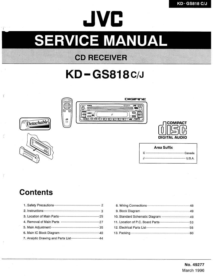
Jvc KDGS 818 Service Manual

This is the 76 pages manual for Jvc KDGS 818 Service Manual.
Read or download the pdf for free. If you want to contribute, please mail your pdfs to info@audioservicemanuals.com.

Page: 1 / 76
left right
Jvc KDGS 818 Service Manual

Extracted text from Jvc KDGS 818 Service Manual (Ocr-read)


Page 1

KD- 68818 C/J

Q
§
E

\

i/i

Contents

1 , Safety Precautions ..................................
2 Instructions ............................................

3. Location of Main Parts -------------------
4. Removal of Main Fans
5. Main Adjustment -----------------
6. Main IC Biock Diagram ..............
7. Analytic Drawing and Pans List-n

~27

@figfi

DIGITAL AUDIO

Area Suffix

c ........................................ Canada
J ........................................... U.S.A.

3 Wiring Connections ................................... 48
9. Block Diagram ................................................. 4g
10. Standard Schematic Diagram ~~~~~~~~~~~~~~~~~~~~~~~~~~~~ 4g
11. Location of P.C. Board Parts» ----------------- 53
12, ElectricaI Parts List ........................................ 55
13 Packing ........................................................ 50

No.'49277

March 1996

Page 2

-KD - G8818 CA]
1. Safety Precautions

IMPORTANT FOR LASER
PRODUCTS (For U.S.A. only)
Precautions

1. CLASS 1 LASER PRODUCT

2. DANGER: Invisible laser radiation when open
and interlock failed or defeated. Avoid direct
exposure to beam.

3. CAUTION: Do not open the top cover. There
are no user-serviceable parts inside. Leave
all servicing to qualified service personnelt

4. CAUTION: This CD player uses invisible laser
radiation, however, is equipped with safety
switches to prevent radiation emission when
unloading 005. it is dangerous to defeat the
safety switches.

5. CAUTION: Use of controls, adjustments or
performance of procedures other than those
specified herein may result in hazardous
radiation exposure.

Identification And Certification Labels

US JVC CORP. 41 SLATER DRIVE
ELMWOOD PARK, N.Ji 07407
MANUFACTURED AT
MADE IN

Product complies with DHHS Rules 21

CFR Subchapter J in effect at date of
manufacture.
MANUFACTURED

N ates:

'1 The date of manufacture.

2 The ID code of manuiacturing plant.
'3 Marking of country origin.

Bottom panel oi the main unit

E]

NAME/RATING PLATE

A CAUTION

system.

Burrs formed during molding may be left over on some parts of the chassis.
Therefore, pay attention to such burrs in the case of preforming repair of this

2 (No. 49277)

Page 43

I l0601: LC72362N (CENTRAL PROCESSING UNIT)

Desorption of pin function

KD - G8818 C/J

No. Pin cord Description No. Pin cord Description
1 Xin 4.5 MHz crystal oscillator connection pin 41 BAND 2 MW/LW band select signal output
2 GND 42 BAND 1 FM/AM band select signal output
3 E .VOLUME IN Electronic volume data input 43 A60 AGC control signal output H
4 E .VOLUME so Electronic volume data output 44
5 E .VOLUME 30 Electronic volume clock output 45 RESR Microcomputer reset pin L
6 EJECT Eject key input L 46 P, SAVE 1 Power save detection 1 L
7 GND 47 SD SD (station detector) signal input H
a LCD so LCD driver data output 48 MOIST Mono control signal output: H: Stereo signal input: L
> 9 LCD SCK LCD driver clock output 49 BEST Rest switch detection L
10 ccE Chip enable signal output to T09284 L 50 L ,FINISH Loading complete switch detection L
1 1 BUS 0 Data output 0 to T053284 51 L .START Loading start switch detection H
12 BUS 1 Data output 1 to TCQ284 52 DISC SELECT 8 cm disc selection detected L
13 BUS 2 Data output 2 to T09284 53 VOISE REST UPD7758 reset signal L
14 BUS 3 Data output 3 to T09284 54 DETACH Front panel detach detection H
15 BUCK Communication clock output to T09284 55 REMOCON Remote control signal input
16 LSI REST Reset signal output to T09284 L 56 P. SAVE 2 Power save detection 2 L
17 LM 0 Loading motor control signal output (fwd) H 57 LCD CE Chip enable signal output to LCD driver L
18 LM 1 Loading motor control signal output (rev) H 58 CD ON CD power control signal output H
19 CD REMOTE CD play remote output H 59 RELAY Power relay control signal output L
20 TUNER Tuner ON remote output H 60 MUTE Voice muting control signal output L
21 INH LCD inhibit output (LCD display ON/OFF) H 61 KEY 0 Key AD input pin 0
22 62 KEY 1 Key AD input pin 1
23 KS 3 initial setting output pin 3 63 KEY 2 Key AD input pin 2
24 KS 2 Initial setting output pin 2 64 KEY 3 Key AD input pin 3
25 KS I Initial setting output pin 1 65 LEVEL. IND. Level meter AD input pin
26 KS 0 Initial setting output pin 0 66 SM S meter (signal intensity) signal input
27 K 5 Initial setting input pin 3 67
28 K2 Initial setting input pin 2 68 SENS Power reduction sense pin L
29 K1 Initial setting input pin 1 69 AM IF COUNT AM IF count signal input
30 K 0 Initial setting input pin 0 70 FM iF COUNT FM iF count signal input
31 Vdd Power supply 71
32 BUSY UPD7758 voice output detection input L 72
33 START UPD7758 voice output start input L 73 Vdd Power supply pin
34 | 5 Data output 5 to UPD7758 74 AM 080 AM local oscillator signal input
35 I4 Data output 4 to UPD7758 75 FM OSC FM local oscillator signal input
36 13 Data outputs to UPD77SB 76 GND Ground pin
37 I 2 Data output 2 to UPD7758 77
38 I 1 Data output 1 to UPD1758 78 ERROR OUT PLL error signal output
39 ID Data output 0 to UPD7758 79 GND
40 IF RQ IF count request output H 50 X out 4.5 MHz crystal oscillator connection pin

(No. 49277) 43