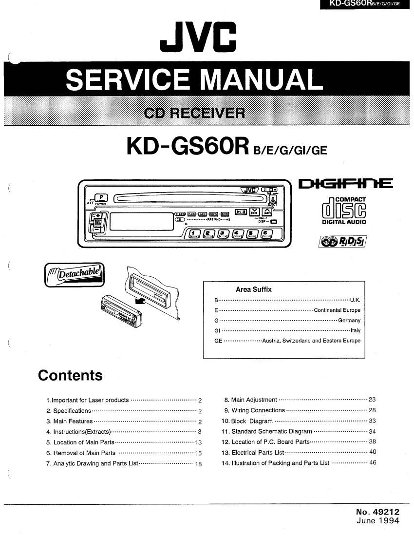
Jvc KDGS 60 R Service Manual

This is the 62 pages manual for Jvc KDGS 60 R Service Manual.
Read or download the pdf for free. If you want to contribute, please mail your pdfs to info@audioservicemanuals.com.

Page: 1 / 62
left right
Jvc KDGS 60 R Service Manual

Extracted text from Jvc KDGS 60 R Service Manual (Ocr-read)


Page 1

xx

,/\

. n

o

9-:
'W'D DIGITAL AUDIO

[@EIQléli

Contents

1.|mportam for Laser products ---------------------------------- 2
2, Specifications ...................................................... 2
3. Main Features ..................................................... 2
4. |nstructions(Extracts) ............................................ 3
5. Location of Main Parts ---------------- -..13
6. Removal of Main Parts ...................................... 15
7. Analytic Drawing and Parts List ............................ 18

Area Suffix

B ........................................................................ U.K,

E .................................................... Continental Europe

G Germany

GI ......... Italy

GE -------------------- Austria, Swiizerland and Eastern Europe
8, Main Adjugtmem .............................................. 23
9_ Wiring Connections .......................................... 28
10. Block Diagram ................................................ 33
11. Standard Schematic Diagram - 34
12. Location of RC. Board Parts ----------------------------- 38
13. Electrica| Pans Liar ........................................... 40
14. Illustration of Packing and Parts List ------------------ 46

No. 49212
June 1994

DIGIFII'I-E

4: COMPACT

imam" . .5

Page 2

bbURB/E/c/ei/ee

1. Important for Laser Products

Position and Reproduction of Labels

UMBER: Invidhll hill WWW MING: 09ml ml» VARI): ia SW

Bottom panel oi the main unit

radiation when mam] stilling vetl ihnma. M1 :tdlnillv nil denim dsl ilhlhttfi DB

CLASS 'I

madam Wand: iwmmi alttiina rdkymgnamalie
wnmm Illtlnm.W9llids¢t~ urhnpvlad. serum e] lasesateilyllz, All M50
mm (a) minim. (d) sullen. (5) master it}

Precautions

1. CLASS 1 LASER PRODUCT

2. DANGER: Invisible laser radiation when
open and interlock failed or defeated. Avoid
direct exposure to beam.

3. CAUTION: Do not open the top cover. There
are no user-serviceable parts inside. Leave
all servicing to qualified service personnel.

4. CAUTION: This CD player uses invisible
laser radiation, however, is equipped with
safety switches to prevent radiation emission
when unloading CDs. It is dangerous to
deleat the safety switches.

5. CAUTION: Use of controls. adjustments or
performance 01 procedures other than those
specified herein may result in hazardous
radiation exposure.

2. Specifications

CD PLAYER SECTION

Type: Compact disc player

Signal Detection System: Non-contact optical pickup
(semiconductor laser)

Number ol Channels: 2 channels (stereo)

Frequency Response: 5 to 20,000 Hz

Dynamic Range: 95 dB

Signal-thoise Ratio: 97 dB

Wow at Flutten Less than measurable limit

AUDIO AMPLIFIER SECTION

Maximum Power Output: (Front) 22 W per channel
(Rear) 22 W per channel

Continuous Power Output (HMS): (From) 8 W per
channel into 4 n. 40 to 20,000 Hz at no more than
0.8% total harmonic distortion, (Rear) 8 W per
channel into 4 Q, 40 to 20,000 Hz at no more than
0.8% total harmonic distortion.

3. Main Features

0 Detachable Control Panel

0 "Direct-in" disc loading system

0 Direct Access Play/Skip Play/Search Play/
Repeat Play/Random Play

0 Radio Data System (RDS)

0 High Sensitivity Tuner

I AM/FM Stereo PLL Synthesizer Tuner

0 its-Station Preset Tuning (FM-12, AM [MW/
LW1-6)

o Seek/Manual Tuning

- Strong~station Sequential Memory (SSM)

o 4-Channel Amplifier System

0 Maximum Power Output of 22 watts per
channel (From/22 watts per channel (Rear)

0 Digital Clock Display

a Line Output Terminal

2 (No. 49212)


LASER PRODUCT

Obs

Apparaten innehaller laser-
komponenl av hdgre laserklass
en kiss 1.

Load Impedance: 4 n (4 to 8 n allowance)
Tone Comrol Range

Bass: :10 dB at too Hz

Treble: i1 0 dB at 10 kHz
Frequency Response: 40 to 20,000 Hz
Signal-to-Noise Ratio: 70 dB
Line-Out Level: 1.5 V/2O k9 load (Full scale)
Output Impedance: 1 kn

RADIO SECTION

Frequency Range
FM: 87.5 to 103.0 MHZ
AM: (MW) 522 to 1,620 kHz \

(LW) 144 to 279 kHz

[FM Tuner]

Usab|e Sensitivity: 12.1 dBl ( 1.1 pV/75 Q)

50 dB Quieting Sensitivity: 16.3 (181 (1.8 uVI75 0)

Alternate Channel Selectivity: (400 kHz): 65 dB

Frequency Response: 40 to 15,000 Hz

Stereo Separation: 30 dB

Capture Ratio: 1.5 dB

[MW Tuner]

Sensitivity: 20 MV

Selectivity: 35 dB

[LW Tuner]

Sensitivity: 50 "V

Page 7

KD-GSGURB/E/o/ci/oe

(RADIO OPERATION
Operate In the order shown.
0 POWER 0 9 BAND F1 0 v
:2 El
m t n. -1»
AM I l
Switch on. Set Tuner mode. Select band. Tune.
Einschalten. Auf Radiobetrieb schelien Den Empiangsbereich einstellen. Abstimmen,
Melt/e en Marsha. Passer on made radio Selectionner Ia gamme. Syntanrser.
SEL BASS/TRE/FA D/BAL/LOUDNOL


Einstellen.
Reg/er.

See page ta.
Siehe Seite 18.

Voirpaga 1.9.

K

Press to move to lower frequencies. ---"\E

g" Press to move to higher lrequencies

Seek Tuning

Press the A or V button for one second or
more; the unit enters the seek tuning mode and
tunes to higher or lower frequencies, and when
the broadcast is received, it stops tuning
automatically and the broadcast can be heard. ln
AM operation. the frequency continuously moves
tram the MW to Lw band and vice versa.

6) (D
W 528$

I035

Manual Tuning

Each time the Tuning button (A or V) is
pressed, the unit steps through the current
frequency band.

Frequency scan steps are as follows:
F - in 50 kHz units
MW/LW - in 9 kHz units

In AM operation, the irequency continuously
moves from the MW (522 to 1,620 kHz) to LW
(144 to 279 kHz) band and vice versa.

Preset Button Tuning

How to Preset Stations
6 stations in each band (FM1. FM2 and AM
[MW/LW]) can be preset as follows:

G Select the FM2 band using the Band (BAND)
button.

® Tune to the desired station.

(9 Press Preset Station button "5" tor more than
2 seconds. (When "PS" blinks in the Preset
Station display, the station is preset.)

0 Repeat the above procedure tor the other 5
Preset Station buttons and other bands
(FMt and AM [MW/LWJ).

Notes:

0 A previously preset station is erased when a
new station is stored in memory.

oThe preset stations are erased when the
power supply to the memory circuit is
interrupted during battery replacement, etc.
When this occurs, preset the stations again.

(No, 49212) 7