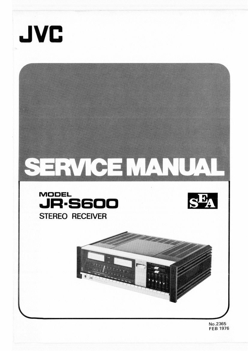
Jvc JRS 600 Service Manual

This is the 55 pages manual for Jvc JRS 600 Service Manual.
Read or download the pdf for free. If you want to contribute, please mail your pdfs to info@audioservicemanuals.com.

Page: 1 / 55
left right
Jvc JRS 600 Service Manual

Extracted text from Jvc JRS 600 Service Manual (Ocr-read)


Page 2

JR-SGOO
No.2365

Contents

Page
1. Specifications ........................................................ 2
2. Level Diagram ........................................................ 3
3. Removal of Top Cover, Bottom Plate and Front Panel .............................. 4
4. Main Parts Location .................................................... 6
5. Exploded View and Parts List
5-(1) Front Panel ................................................... 7
5-(2) Rear Panel .................................................... 8
6. Dial Stringing Procedure ................................................. 9
7. FM/AM Tuner Alignment Procedures
7-(1) FM Section ................................................... 10
7-(2) AM Section ................................................... 13
8. Power Amplifier Adjustment Procedure
8-H) Center Voltage ................................................. 14
8-(2) Idling Current ................................................. 14
8-(3) Power Meter .................................................. 15
9. Circuit Board Ass'y Parts List
9-(1) TSC-34B Driver Amp. Base C.B. Ass'y ................................. 15
9-(2) TSC<37B Driver Amp. Base 6.8. Ass'y ................................. 17
9-(3) TPS-47 Equalizer Power Supply C.B. Ass'y .............................. 18
9-(4) TPS-48 AC Block C.B. Ass'y ....................................... 1g
9-(5) TP849 Fuse C.B. Assy ........................................... 20
946) TPSSO Meter Lamp C.B. Ass'y ...................................... 20
9-17) TPS-51 Source Lamp C.B. Assy ..................................... 21
9-(8) TAE-118 Equalizer Amp. C.B. Ass'y .................................. 22
9-(9) TAD-1693 Driver Amp. C.B. Ass'y ................................... 25
9-(10) TAD-174 Driver Amp. C.B. Ass'y .................................... 28
9-(11) TAO-402B S.E.A. (Sound Effect Amp.) Volume C.B. Ass'y ................... 31
9-(12) TAC~405 FM Noise Reduction 03. Ass'y ............................... 33
9-(13) TAG-406 S.E.A. (Sound Effect Amp.) Amp. 03. Assy ..................... 38
9414) TAO-407 Selector C.B. Assy ....................................... 41
9-(15) TAG-408 Speaker C.B. Ass'y ....................................... 42
9-(16) TFM-91OGUA2 FM/AM Tuner C.B. Assy .............................. 43
10. Packing Materials List ................................................... 48
11. Accessories Li'st ....................................................... 43
12. Transistor, IC and Diode Lead Identification .................................... 49
13. Schematic Diagram ..................................................... 50
14. Parts List with Specified Numbers for Designated Areas ............................. 52

Page 18

9-(2) TSC-37B

MARK"


Driver Amp. Base 0.3. Ass'y

Precaution

Reconnect the female plug to a
proper position as indicated
"MARK. Refer to Fig. 308.

7pins
73000000

Top View or TSC-37B

Fig. 3043

...........

Mb...

* i
c 00:.

)DOB'
..°6;°' Z.-

I . 2 . ' ' '
_ " _ .2 409 l.
04!!
k I i
7 .1
Fig. 31
Transistors
Item No. Part Number Rating Description Maker
Pc fT
X001 28D425 (O) 100W 6MHz Silicon Toshiba
X003 238555 (0) " "
X005 25D425 (O) " " " "
X007 258555 (0) " " "
X415 28C853 (M) 400mW " NEC
Capacitors
Item No. Part Number Rating Description Maker
C409 QFM42AK-224 0,22uF 10V Mylar
C413 QFM42AK-224 "
Others
Item No. Part Number Rating Description Maker
E03606-001 Male Contact Pin
E03677-002 Transistor Socket
E21824-002 Heat Sink
E34120-002 Bracket
E34412-002 Heat Sink Bracket
E49784-002 Contact Pin
JR-SGOO
No.2365 o 17 _