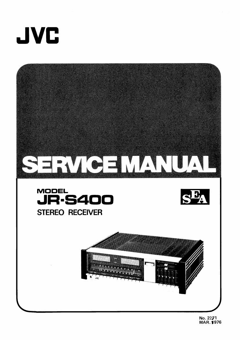
Jvc JRS 400 Service Manual

This is the 51 pages manual for Jvc JRS 400 Service Manual.
Read or download the pdf for free. If you want to contribute, please mail your pdfs to info@audioservicemanuals.com.

Page: 1 / 51
left right
Jvc JRS 400 Service Manual

Extracted text from Jvc JRS 400 Service Manual (Ocr-read)


Page 2

Contents

Page
1. Specifications ........................................................ 2
2. Level Diagram ......................... 3
3. Removal of Top Cover, Bottom Plate and Front Panel .............................. 4
4. Main Parts Locations .................................................... 6
5. Exploded View and Parts List
5(1) Front Panel ................................................... 7
5-(2) Rear Panel .................................................... 3
6. Dial Stringing Procedure ................................................. 9
7. FM/AM Tuner Alignment Procedures
7-) FM Section ................................................... 10
7-(2) AM Section ................................................... 12
8. Power Amplifier Adjustment Procedures
8-H) Center Voltage ................................................. 13
8-(2) ldlingCurrent ............ 13
8-(3) Power Meter .................................................. 14
9. Circuit Board Ass'y Part Locations and Parts List
9-(1) TPS-48 AC Block C.B. Ass'y ....................................... 15
9-(2) TPS-49C Fuse C.B. Assy .......................................... 15
9-(3) TPS-SOB Meter Lamp C.B. Assy ........ , .............................. 1 6
9-(4) TPS-GBA Stabilizer C.B.Ass'v ...................................... 16
945) TAP-258 Power Amp. C.B. Assy .................................... 17
9-(6) TAP-259 Power Amp. C.B. Assy .................................... 19
9-(7) TAP-260 Power Supply C.B. Assy ................................... 22
9-(8) TAG-4023 S.E.A. (Sound Effect Amp.) Control C.B. Assy ................... 24
9-(9) TAG-406 S.E.A. (Sound Effect Amp.) Amp. C.B. Ass'y ..................... 26
9-(10) TACAOSB Speaker C.B. Ass'y ...................................... 29
9-(11) TAO-414 Selector C.B. Assy ....................................... 30
9-(12) TFM-91OGUA2 FM/AM Tuner C.B. Ass'y .............................. 33
10. Packing Materials List ................................................... 38
11. Accessories List ....................................................... 38
12. Transistor, LC. and Diode Lead Identification ................................... 39
13. Parts List with Specified Numbers for Designated Areas ............................. 40
14. Schematic Diagram ..................................................... 41

JR-S400
No. 2371