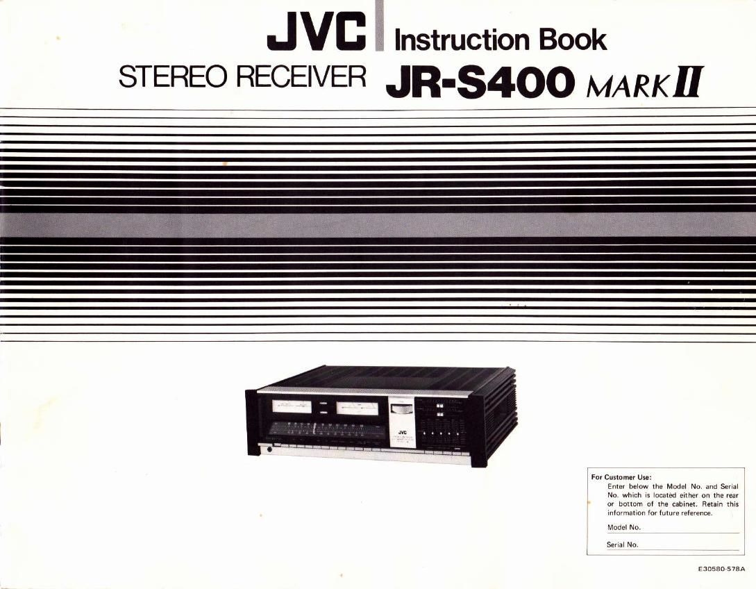
Jvc JRS 400 Mk2 Owners Manual

This is the 12 pages manual for Jvc JRS 400 Mk2 Owners Manual.
Read or download the pdf for free. If you want to contribute, please mail your pdfs to info@audioservicemanuals.com.

Page: 1 / 12
left right
Jvc JRS 400 Mk2 Owners Manual

Extracted text from Jvc JRS 400 Mk2 Owners Manual (Ocr-read)


Page 1

AGdJeToTlfs hstruction Elook Thank you for buyins JVC'S JRS400 [4ARK II Stereo Receiver. You are now th-ぎ owner of a sophhticated stereo receivff incorporating many advanced featuros, This book is divid-ぎd into two section!. The first der_ crib$ basic functions listenino to radio broadcasts, playing records and tap-ぎs and r-ぎpording tapes. The r-ぎcond section describes the more advanced functions, S.E.A., tape dubbing, the attachment of other devices, Befor-ぎ you read these, you should r-ぎad the precautions. Whhiog you h.ppy and succersful lirtening. CONTENTS lmponant . . Front panel . Conneclion diasram Connecting speakeu Anlennas . . A33ic L:sreling ro Alvl b'oadcdn L srening ro Flvl broadcast Lisiening 1o reco.ds Listenrng to tapes Recordinq tapes S.E.A. recbding IMPORTANT 1. lnsull.tion . Select a place which is level, dry and neither too hot nor too cold {between 5' and 40'c/23"F aod rear of the re-ぎeiver and to block the ventilation IMPORTANT (ln the United Kingdom) Mains Supply (240V 50Hz Ac onlyl Warning: Thia apparatus must be earthed t04"F). Leave . space between the Oo not allow a curtain,etc, Keep the receiver away from direct tunlight. Do not put it too close to a heater. Do not use it in a place subject to vibrations. Do not use it wherc it is dusty. Keep it 6s far lrom vour TV as possible. Check that the receiver is set for your local supply vohage and frequency. lf not, consult the dealer from whom vou bousht it. Thk unit has a three-core mains lead which should b-ぎ fitted with a 3-pin plus. The wir-ぎs in the main lead are coloured i^ accordance with following code: Bl0-ぎ ro N (Nsutr.l)or alack Brown ro L (l-iv.)or Fed Gr-ぎen/Yellow to E.rrh or 6re-ぎ. 2. I 2 3 4 4 . Do not handle the power cord with w-ぎt handrl . Oo not bend the power cord sharply- . When unplussing from the wall outlet, always pull the plug, not the power cod. 3. M.lfunctioni, etc. . There are no user rerviceable panr inside. lf any' thing goes wrong, unplug the power cord and consult . Do nor insert any meta'lic object inside the receiver. . Do not allow water to set inside the receiver. . This receiver cont8ins a protective circuit which interupts the sound when h operates. lf the sou6d from your receiver h intermittent, it could be b-ぎcause of the operation of thk circuit. ln this case you should consult your dealer. lf these colouls do not correspond with the terminal identifications of your plug, connect as follows: Blue wire to t-ぎrminal coded N {Neutral) or coloured Brown wire to rerminal coded L (Live) or coloured Red Gr-ぎen/Yellow wire to the larger terminal coded E or Green. lf in .loubt - consuh a compebnt electician. We recommend that vou shouid disconnect the AC cord 5 5 6 6 6 6 6 Uring stereo headphones S.E.A. P'eser p/rre,^s Some more about S.E.A. Powe'meiers Tapedubbing. Con4ectingnoisereductionunit ........ . Us'nsP,eOut/lvlainlnterminak ........... Flvl Det OJt . Troubles1oot'ng Specilrcarions 7 7 I I I 9 9 10 10 WARNING: TO PREVENT FIRE OR SHOCK HAZARD, DO NOT EXPOSE THIS APPLIANCE TO RAIN OR MOISTURE. CAUTION shock, do not No user serviceable parts inside. Reter servicing qualif ied seryice personnel. 1-

Page 2

FROT{T PANEL L SIGNAL ltrength mster This is used in tuning to broadcasts, both FI\I and AlVl. lt makes its maximum deflection when the strength of the signal being received is greatest, i.e. when you are correctly tuned to a broadcast. 2. Flvl TUNING metor Th's is used in tuning to FIV broddcasts. lt sw ngs to the center position when yo! are tuned to the center frequency of the broadcast. 3. FM STEREO indicator 4. POWER ON/OFF indicator This lamp lights up when the POWER switch is 5. POWER meter3 Thes-ぎ mete6 indicate the output power in watts rather than the lsual VIJ or uncalibrated unit'. The values in watti are indicared when one pair of speakers having an impedance of exactly 8 ohms is beins driven. (See paqe 8.) 6. TUNING conr.ol T!rd lightly to tune to Aftl and FM broadcarts. 7. VOLUME control Slide to the right to hear louder sound. 8. BALANCE control Thk adjusts the balance between rhe left and right speakers. When it is at the left, you can hear onty the left channel. When it is at the right, you can hea. only the right channel. 9. S.E.A. Grsphic Equalizor tone control system These five controk allow vou to boost and lower five sections of the frequency range by 12dB independently. For operation of these controk, which give far more flexible controt over tone than the conventional basshreble controls, see page 7. The preset patterns add to your listening pteasure with different types of mosic. 23. 15. Tuning dial llluminated dial point.r Headphone jack (PHONES) Plug stereo headphones into this jack for private istening and recording monitoring. See page 6. SPK-2 lwitch Press to switch the speakers connected to the Speaker System 2 terminals oh and off. Press to switch on AM tuner section. Press to switch on Flvl tuner section. PHONO-1 iwitch Press to hear sound connected to PHoNo-l ter, mi.als on the rear panel. PHONO2 3witch Pfess to hear soond connected to PHoNo,2 tef minals on the rear panel. AUX switch Pres' to hedr 5ound connecred to AUX term ^a's. TAPE-l/EXT.NR 3wirch Press to hear tape deck connected to the TAPE,I terminals. When an external noise reducrion unit is connected, this switch should be pressed in for its TAPE-2 twitoh Press to hear tape d-ぎck connected to the TAPE.2 terminals or TAPE-2 DIN socker. FM mutinsy'mode swirch IFM MUTE OFF/MONO) This controls the Fl\,4 muring circuit and atso acis as the mono/srereo mode switch_ When it is in, a mi)(ture of right and left channet sound wi| be heard from both speakeG even:t broddcasting is don-ぎ in stereo. lf it is pressed in when the reception of an FM stereo broadcast is sub.standard. it aho switches off the FM muring cjrcuit. LOUDNESS switch At low volumes, the tone of sound appea.s to change. This is not due to any change in the sound itself, but due to the eart different sensitivity to sound at low volumes. Press to compensate for this when you are listening at low volumes. LOW FILTER switch Press to cut excessive bas or low frequencv noise_ HIGH FILTER lwitch Press to cut hiqh frequency hiss or record surface S.E.A. REC awiich Press to record tapes with the added effect of the S.E.A. Graphic Equalizer. 16. 17. 18. 10. 11. 12. 24. Pres to switch the power 06 and off. After the POWER switch is turned ON, no sound will be head lor 3 4 seconds. The protecrive circuit relay operates to put the circuitry ontine. You will hear a click from the retay operation at this time. This is not due to any defect in the ser. 14. SPK-l switch Press to switch the speakers connected to the Speaker Svstem I terminats on and ofr 20. 21. 19. 25. 26. 22. 27.