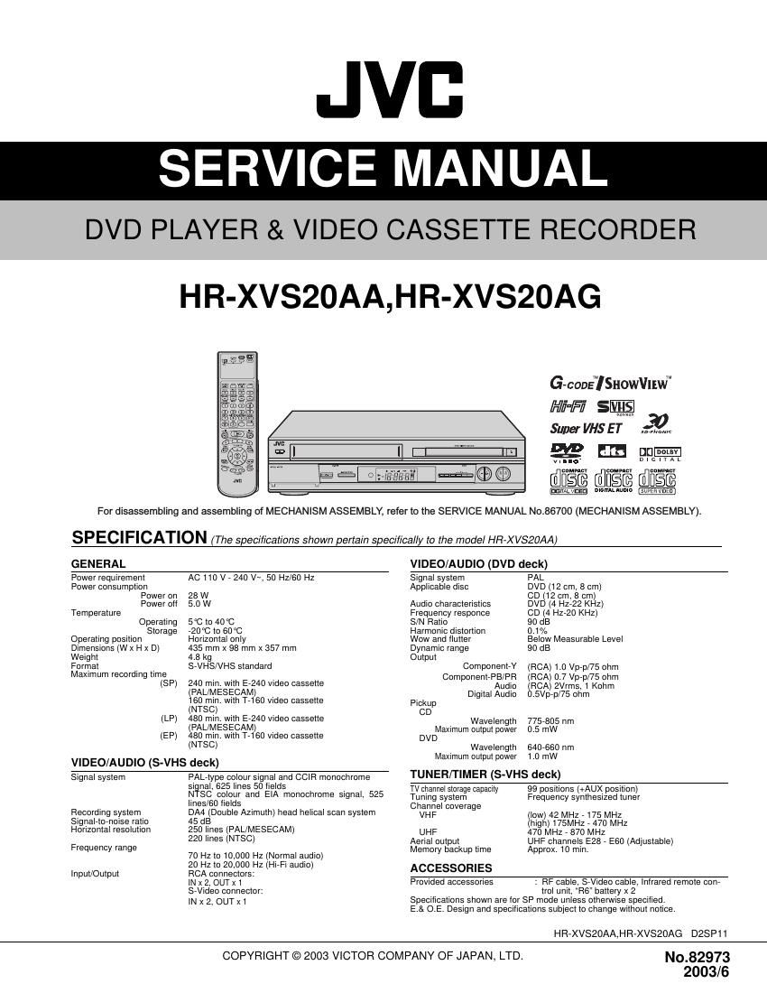
Jvc HRXVS 20 AA Service Manual

This is the 30 pages manual for Jvc HRXVS 20 AA Service Manual.
Read or download the pdf for free. If you want to contribute, please mail your pdfs to info@audioservicemanuals.com.

Page: 1 / 30
left right
Jvc HRXVS 20 AA Service Manual

Extracted text from Jvc HRXVS 20 AA Service Manual (Ocr-read)


Page 1

1-2 (No.82973) The following table indicates main different points between models HR-XVS20AA and HR-XVS20AG. MODEL ITEMHR-XVS20AA HR-XVS20AG POWER PLUG SAA CEE RF OUT CH/RF OUT SYSTEM [INITIAL] 28-60[36]/G, [H], K, I 28-60[36]/[G] ,H ,K, I OSD LANGUAGE ENGLISH ENGLISH, RUSSIAN REGION NUMBER REGION NUMBER 4 REGION NUMBER 3

Page 2

(No.82973)1-3 TABLE OF CONTENTS 1 PRECAUTIONS . . . . . . . . . . . . . . . . . . . . . . . . . . . . . . . . . . . . . . . . . . . . . . . . . . . . . . . . . . . . . . . . . . . . . . . 1-4 1.1 SAFTY PRECAUTIONS. . . . . . . . . . . . . . . . . . . . . . . . . . . . . . . . . . . . . . . . . . . . . . . . . . . . . . . . . . . . 1-4 2 SPECIFIC SERVICE INSTRUCTIONS . . . . . . . . . . . . . . . . . . . . . . . . . . . . . . . . . . . . . . . . . . . . . . . . . . . . . . 1-9 2.1 Manually removing the cassette tape. . . . . . . . . . . . . . . . . . . . . . . . . . . . . . . . . . . . . . . . . . . . . . . . . . 1-9 2.2 Manually removing the disk(DVD/CD) . . . . . . . . . . . . . . . . . . . . . . . . . . . . . . . . . . . . . . . . . . . . . . . . . 1-9 2.3 Removing the major parts . . . . . . . . . . . . . . . . . . . . . . . . . . . . . . . . . . . . . . . . . . . . . . . . . . . . . . . . . 1-10 2.4 DVD unit . . . . . . . . . . . . . . . . . . . . . . . . . . . . . . . . . . . . . . . . . . . . . . . . . . . . . . . . . . . . . . . . . . . . . . . 1-12 2.5 Emergency display function . . . . . . . . . . . . . . . . . . . . . . . . . . . . . . . . . . . . . . . . . . . . . . . . . . . . . . . . 1-18 2.6 Service position (VHS) . . . . . . . . . . . . . . . . . . . . . . . . . . . . . . . . . . . . . . . . . . . . . . . . . . . . . . . . . . . . 1-23 2.7 Jig RCU mode . . . . . . . . . . . . . . . . . . . . . . . . . . . . . . . . . . . . . . . . . . . . . . . . . . . . . . . . . . . . . . . . . . 1-23 2.8 Mechanism service mode . . . . . . . . . . . . . . . . . . . . . . . . . . . . . . . . . . . . . . . . . . . . . . . . . . . . . . . . . 1-24 2.9 Maintenance and inspection . . . . . . . . . . . . . . . . . . . . . . . . . . . . . . . . . . . . . . . . . . . . . . . . . . . . . . . 1-24 2.10 Test mode (DVD) . . . . . . . . . . . . . . . . . . . . . . . . . . . . . . . . . . . . . . . . . . . . . . . . . . . . . . . . . . . . . . . 1-24 3 ADJUSTMENT . . . . . . . . . . . . . . . . . . . . . . . . . . . . . . . . . . . . . . . . . . . . . . . . . . . . . . . . . . . . . . . . . . . . . . . 1-25 3.1 Before adjustment . . . . . . . . . . . . . . . . . . . . . . . . . . . . . . . . . . . . . . . . . . . . . . . . . . . . . . . . . . . . . . . 1-25 3.2 Mechanism compatibility adjustment . . . . . . . . . . . . . . . . . . . . . . . . . . . . . . . . . . . . . . . . . . . . . . . . . 1-26 3.3 Electrical adjustment . . . . . . . . . . . . . . . . . . . . . . . . . . . . . . . . . . . . . . . . . . . . . . . . . . . . . . . . . . . . . 1-28 CHARTS AND DIAGRAMS BOARD INTERCONNECTIONS . . . . . . . . . . . . . . . . . . . . . . . . . . . . . . . . . . . . . . . . . . . . . . . . . . . . . . . . . . 2-3 SWITCHING REGULATOR SCHEMATIC DIAGRAM. . . . . . . . . . . . . . . . . . . . . . . . . . . . . . . . . . . . . . . . . . 2-5 MAIN (VIDEO/N.AUDIO) SCHEMATIC DIAGRAM . . . . . . . . . . . . . . . . . . . . . . . . . . . . . . . . . . . . . . . . . . . . 2-7 MAIN (S-SUB) SCHEMATIC DIAGRAM . . . . . . . . . . . . . . . . . . . . . . . . . . . . . . . . . . . . . . . . . . . . . . . . . . . . 2-9 MAIN (2D DIGITAL) SCHEMATIC DIAGRAM. . . . . . . . . . . . . . . . . . . . . . . . . . . . . . . . . . . . . . . . . . . . . . . 2-11 MAIN (FMA) SCHEMATIC DIAGRAM. . . . . . . . . . . . . . . . . . . . . . . . . . . . . . . . . . . . . . . . . . . . . . . . . . . . . 2-13 MAIN (SYSCON) SCHEMATIC DIAGRAM . . . . . . . . . . . . . . . . . . . . . . . . . . . . . . . . . . . . . . . . . . . . . . . . . 2-15 MAIN (CONNECTION) SCHEMATIC DIAGRAM . . . . . . . . . . . . . . . . . . . . . . . . . . . . . . . . . . . . . . . . . . . . 2-17 REMOTE CONTROLLER SCHEMATIC DIAGRAM . . . . . . . . . . . . . . . . . . . . . . . . . . . . . . . . . . . . . . . . . . 2-18 FDP GRID ASSIGNMENT AND ANODE CONNECTION . . . . . . . . . . . . . . . . . . . . . . . . . . . . . . . . . . . . . . 2-18 MAIN (TUNER) SCHEMATIC DIAGRAM . . . . . . . . . . . . . . . . . . . . . . . . . . . . . . . . . . . . . . . . . . . . . . . . . . 2-19 MAIN (FRONT), FRONT, JACK AND ADV.JOG SCHEMATIC DIAGRAMS . . . . . . . . . . . . . . . . . . . . . . . 2-21 MAIN (TERMINAL) SCHEMATIC DIAGRAM . . . . . . . . . . . . . . . . . . . . . . . . . . . . . . . . . . . . . . . . . . . . . . . 2-23 DEMODULATOR SCHEMATIC DIAGRAM. . . . . . . . . . . . . . . . . . . . . . . . . . . . . . . . . . . . . . . . . . . . . . . . . 2-25 DVD IF SCHEMATIC DIAGRAM . . . . . . . . . . . . . . . . . . . . . . . . . . . . . . . . . . . . . . . . . . . . . . . . . . . . . . . . . 2-27 DVD SERVO CONTROL SCHEMATIC DIAGRAM . . . . . . . . . . . . . . . . . . . . . . . . . . . . . . . . . . . . . . . . . . . 2-29 DVD AV DECODER SCHEMATIC DIAGRAM . . . . . . . . . . . . . . . . . . . . . . . . . . . . . . . . . . . . . . . . . . . . . . 2-31 DVD FLASH ROM SCHEMATIC DIAGRAM . . . . . . . . . . . . . . . . . . . . . . . . . . . . . . . . . . . . . . . . . . . . . . . . 2-33 VOLTAGE CHARTS . . . . . . . . . . . . . . . . . . . . . . . . . . . . . . . . . . . . . . . . . . . . . . . . . . . . . . . . . . . . . . . . . . 2-35 FRONT AND JACK CIRCUIT BOARDS . . . . . . . . . . . . . . . . . . . . . . . . . . . . . . . . . . . . . . . . . . . . . . . . . . . 2-37 SWITCHING REGULATOR AND DEMODULATOR CIRCUIT BOARDS . . . . . . . . . . . . . . . . . . . . . . . . . . 2-38 COMPONENT PARTS LOCATION GUIDE LPB10194-001C . . . . . . . . . . . . . . . . . . 2-38 COMPONENT PARTS LOCATION GUIDE LPB10184-001C . . . . . . . . . . 2-38 MAIN CIRCUIT BOARD . . . . . . . . . . . . . . . . . . . . . . . . . . . . . . . . . . . . . . . . . . . . . . . . . . . . . . . . . . . . . . . 2-39 COMPONENT PARTS LOCATION GUIDE
LPB10186-001B . . . . . . . . . . . . . . . . . . . . . . . . . . . . 2-41 DVD IF CIRCUIT BOARD . . . . . . . . . . . . . . . . . . . . . . . . . . . . . . . . . . . . . . . . . . . . . . . . . . . . . . . . . . . . . . 2-42 COMPONENT PARTS LOCATION GUIDE LPB10183-001C . . . . . . . . . . . . . . . . . . . . . . . . . . 2-42 DVD SERVO CONTROL AND DVD LOADING MOTOR CIRCUIT BOARDS . . . . . . . . . . . . . . . . . . . . . . 2-43 CPU PIN FUNCTION . . . . . . . . . . . . . . . . . . . . . . . . . . . . . . . . . . . . . . . . . . . . . . . . . . . . . . . . . . . . . . . . . 2-44 SYSTEM CONTROL BLOCK DIAGRAM . . . . . . . . . . . . . . . . . . . . . . . . . . . . . . . . . . . . . . . . . . . . . . . . . . 2-45 AUDIO BLOCK DIAGRAM . . . . . . . . . . . . . . . . . . . . . . . . . . . . . . . . . . . . . . . . . . . . . . . . . . . . . . . . . . . . . 2-46 VIDEO BLOCK DIAGRAM (1) . . . . . . . . . . . . . . . . . . . . . . . . . . . . . . . . . . . . . . . . . . . . . . . . . . . . . . . . . . . 2-47 VIDEO BLOCK DIAGRAM (2) . . . . . . . . . . . . . . . . . . . . . . . . . . . . . . . . . . . . . . . . . . . . . . . . . . . . . . . . . . . 2-49 DVD BLOCK DIAGRAM . . . . . . . . . . . . . . . . . . . . . . . . . . . . . . . . . . . . . . . . . . . . . . . . . . . . . . . . . . . . . . . 2-51 WAVE FORMS . . . . . . . . . . . . . . . . . . . . . . . . . . . . . . . . . . . . . . . . . . . . . . . . . . . . . . . . . . . . . . . . . . . . . . 2-52 PARTS LIST 1. EXPLODED VIEW 1.1 PACKING AND ACCESSORY ASSEMBLY . . . . . . . . . . . . . . . . . . . . . . . . . . . . . . . . . . . . . . . . 3-1 1.2 FINAL ASSEMBLY . . . . . . . . . . . . . . . . . . . . . . . . . . . . . . . . . . . . . . . . . . . . . . . . . . . . . . . . . . . . 3-2 1.3 MECHANISM ASSEMBLY . . . . . . . . . . . . . . . . . . . . . . . . . . . . . . . . . . . . . . . . . . . . . . . . . . . . . . 3-4 1.4 DVD TRAVERSE MECHANISM ASSEMBLY . . . . . . . . . . . . . . . . . . . . . . . . . . . . . . . . . . . . . . . . 3-5 1.5 DVD LOADING MECHANISM ASSEMBLY . . . . . . . . . . . . . . . . . . . . . . . . . . . . . . . . . . . . . . . . . 3-6 2. PARTS LIST PACKING AND ACCESSORY ASSEMBLY . . . . . . . . . . . . . . . . . . . . . . . . . . . . . . . . . . . . . . . . . . . . . 3-7 FINAL ASSEMBLY . . . . . . . . . . . . . . . . . . . . . . . . . . . . . . . . . . . . . . . . . . . . . . . . . . . . . . . . . . . . . . . . 3-7 MECHANISM ASSEMBLY . . . . . . . . . . . . . . . . . . . . . . . . . . . . . . . . . . . . . . . . . . . . . . . . . . . . . . . . . . 3-7 DVD TRAVERSE MECHANISM ASSEMBLY. . . . . . . . . . . . . . . . . . . . . . . . . . . . . . . . . . . . . . . . . . . . . 3-8 DVD LOADING MECHANISM ASSEMBLY . . . . . . . . . . . . . . . . . . . . . . . . . . . . . . . . . . . . . . . . . . . . . . 3-8 SWITCHING REGULATOR BOARD ASSEMBLY <01> . . . . . . . . . . . . . . . . . . . . . . . . . . . . . . . . . . . . . . . . . 3-8 MAIN BOARD ASSEMBLY <03>. . . . . . . . . . . . . . . . . . . . . . . . . . . . . . . . . . . . . . . . . . . . . . . . . . . . . . . . . . . 3-9 A/C HEAD BOARD ASSEMBLY <12>. . . . . . . . . . . . . . . . . . . . . . . . . . . . . . . . . . . . . . . . . . . . . . . . . . . . . . 3-16 DEMODULATOR BOARD ASSEMBLY <14> . . . . . . . . . . . . . . . . . . . . . . . . . . . . . . . . . . . . . . . . . . . . . . . . 3-16 FRONT BOARD ASSEMBLY <28> . . . . . . . . . . . . . . . . . . . . . . . . . . . . . . . . . . . . . . . . . . . . . . . . . . . . . . . . 3-16 S JACK BOARD ASSEMBLY <36> . . . . . . . . . . . . . . . . . . . . . . . . . . . . . . . . . . . . . . . . . . . . . . . . . . . . . . . . 3-16 DVD IF BOARD ASSEMBLY <50> . . . . . . . . . . . . . . . . . . . . . . . . . . . . . . . . . . . . . . . . . . . . . . . . . . . . . . . . 3-16 LOADING MOTOR BOARD ASSEMBLY <55> . . . . . . . . . . . . . . . . . . . . . . . . . . . . . . . . . . . . . . . . . . . . . . . 3-18 DVD SERVO CONTROL BOARD ASSEMBLY <95> . . . . . . . . . . . . . . . . . . . . . . . . . . . . . . . . . . . . . . . . . . 3-18 DVD LOADING MOTOR BOARD ASSEMBLY <96> . . . . . . . . . . . . . . . . . . . . . . . . . . . . . . . . . . . . . . . . . . 3-20

Page 28

(No.82973)1-29 (1) Record the signal (A2) in the mode (B1), and play back the recorded signal. (2) Set the VCR to the manual tracking mode. (3) Set the VCR to the FWD slow (+1/6x) mode. (4) Transmit the code (F) from the Jig RCU to adjust so that the noise bar becomes the specified value (G) on the TV monitor in the slow mode. (5) Set the VCR to the Stop mode. (6) Confirm that the noise bar is (G) on the TV monitor in the slow mode. (7) Repeat steps (3) to (6) in the REV slow (-1/6x) mode. (8) Repeat steps (1) to (7) in the mode (B2). (9) Repeat steps (1) to (8) in the signal (A3). Note: -For FWD slow (+1/6x) playback, transmit the code 08 from the Jig RCU to enter the slow playback mode, and transmit the code D0for REV slow (-1/6x) mode. 3.3.2 Video circuit 3.3.2.1 EE Y/PB Y (S-VHS/VHS) level (1) Input the signal (A3) from the input point (A1). (2) Set the VCR to the mode (B1). (3) Observe the Y OUT waveform at the measuring point (D). (4) Set the VCR to the EVR mode by transmitting the code (F1) from the Jig RCU. (5) Set the EVR address to (F2) by transmitting the code (F3) from the Jig RCU. (6) Transmit the code (F4) from the Jig RCU to adjust so that the Y level of the Y OUT waveform becomes the specified value (G). (7) Release the EVR mode of the VCR by transmitting the code (F1) from the Jig RCU again. (When the EVR mode is released, the adjusted data is memorized.) (8) Input the signal (A3) from the input point (A2). (9) Repeat steps (3) to (7) in the mode (B1). (10) Record the signal (A3) in the mode (B2), and play back the recorded signal. (11) Set the VCR to the manual tracking mode. (12) Repeat steps (3) to (7) in the mode (B2). (13) Record the signal (A3) in the mode (B3), and play back the recorded signal. (14) Set the VCR to the manual tracking mode. (15) Repeat steps (3) to (7) in the mode (B3). Fig.3-3-2a EE Y/PB Y lebel3.3.3 Syscon circuit [EK/EX MODEL] Notes: -When perform this adjustment, remove the Mechanism assembly. 3.3.3.1 Timer clock (1) Connect the frequency counter to the measuring point (D1). (2) Connect the short wire between the short point (D2) and Vcc (5V). (3) Short the leads of capacitor (D3) once in order to reset the microprocessor of the Syscon. (4) Disconnect the short wire between the short point (D2) and Vcc then connect it again. (5) Adjust the Adjustment part (F) so that the output frequency becomes the specified value (G). 3.3.4 Audio circuit Notes: -GND (Ground) should be taken from the Tuner shield case. 3.3.4.1 Audio REC FM (1) Apply the external trigger signal to D.FF (E) to observe the Audio PB FM waveform at the measuring point (D). (2) Record the signal (A3) with no audio signal input in the mode (B), and play back the recorded signal. (3) Set the VCR to the manual tracking mode. (4) If the A.PB FM level is not within the specified value (G1), perform the adjustment in a following procedure. (5) Adjust the adjustment part(F) so that the A. PB FM level of the higher channel level becomes the specified value(G1). (Adjust before recording, then confirm it by playing back.) (6) If specified value(G1) is not obtained, adjust the Adjust- ment part(F) so that the waveform level of the lower chan- nel level becomes the specified value(G2).(Adjust before recording, then confirm it by playing back.) Fig.3-3-4a Audio REC FM Signal (A1) (A2) (A3)- Ext. S-input - Ext. input - Color (colour) bar signal [PAL] Mode (B1) (B2) (B3)- EE SP -S-VHS SP -VHS SP Equipment (C) - Oscilloscope Measuring point (D) - Y OUT terminal EVR mode EVR address(F1) (F2) (F3) (F4)- Jig code 57 - A : 11 - Jig code 21 twice - Jig code 18 or 19 (Channel +/-) Specified value (G) - 1.00 ± 0.05 Vp-p (75 ohm terminated) Adjustment tool (H) - Jig RCU [PTU94023B] H. rate Y level Signal (A1) - No signal Mode (B) - EE Equipment (C) - Frequency counter Measuring point (D1) (D2) (D3)- IC3001 pin 44 - IC3001 pin 103 - C3054 + and - Adjustment part (F) - C3025 (TIMER CLOCK) Specified value (G1) - 1024.008 ± 0.001 Hz (976.5549 ± 0.0010 usec) Signal (A1) (A2) (A3)- Ext. input - Audio: No signal - Video: Color (colour) bar signal [PAL] Mode (B) - S-VHS LP Equipment (C) - Oscilloscope Measuring point (D) - TP2253 (A. PB. FM) External trigger (E) - TP111 (D.FF) Adjustment part (H) - VR2251 Specified value (G1) (G2)- 600 ± 100 mVp-p - More than 400 mVp-p V. rate Specified value (G1) Specified value (G2)