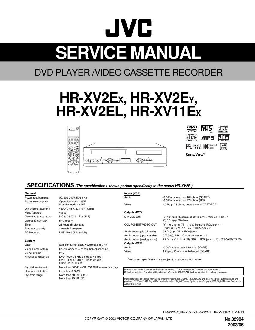
Jvc HRXV 2 E Service Manual

This is the 116 pages manual for Jvc HRXV 2 E Service Manual.
Read or download the pdf for free. If you want to contribute, please mail your pdfs to info@audioservicemanuals.com.

Page: 1 / 116
left right
Jvc HRXV 2 E Service Manual

Extracted text from Jvc HRXV 2 E Service Manual (Ocr-read)


Page 1

CONTENTS SECTION 1 . . . . SUMMARY SECTION 3 . . . . ELECTRICAL SECTION 4 . . . . MECHANISM OF VCR PART SECTION 5 . . . . MECHANISM OF DVD PART SECTION 6 . . . . REPLACEMENT PARTS LIST

Page 2

SECTION 1 SUMMARY CONTENTS Important Safety Precautions SPECIFICATIONS ................................................................................................... 1-5

Page 15

3-10 (4) KEY doesnt working KEY doesnt working. Is 5V applied to the IC501 Pin36? Does LED or FLD change when a function button is pressed? Refer to SMPS 5.3VA Trouble Shooting. Replace the defective switches. YES NO NO

Page 47

4-14 DECK MECHANISM ADJUSTMENT Purpose: To insure smooth transport of the tape during each mode of operation.If the tape transport is abnormal, then check the torque as indicated by\ the chart below. 2. Preparation for Adjustment (To set theDeck Mechanism of the loading state without inserting a cassette tape). 1) Unplug the power cord from the AC outlet. 2) Disassemble the Top Cover and Plate Assembly Top. 3) Plug the power cord into the AC outlet. 4) Turn the power S/W on and push the Lever Stopper of the Holder Assembly CST to the back for loading the cassette without tape. Cover the holes of the End Sensors at the both sides of the Chassis to prevent a light leak. Then the Deck Mechanism drives to the Stop Mode. In this case, the Deck Mechanism can accept inputs of each mode, however the Rewind and Review operation can not be performed for more than a few seconds because the Take-up Reel Table is in the Stop State and can not be detected the Reel Pulses. 3. Checking Torque NOTE: The values are measured by using a Torque Gauge and Torque Gauge Adaptor with the Torque Gauge affixed. NOTE: The torque reading to measure occurs when the tape abruptly changes direction from Fast Forward to Rewind Mode, when quick braking is applied to both Reels. SRKVIDEO CASSET E TORQUEMETER VHT 303 SRK-VHT- S S RK-VHT-T 300250 200 150 50 0 300250 200150 50 0 100 Test Equipment/ Fixture - Torque Gauge(600g/cm ATG) - Torque Gauge Adaptor - Cassette Torque Meter Checking Method - Perform each Deck Mechanism mode withoutinserting a cassette tape(Refer to above No.2 Preparation for Adjustment). - Read the measurement of the Take-up or Supply Reels on the Cassette Torque Meter(Fig. C-3-2). - Attach the Torque Gauge Adaptor to the Torque Gauge and then read the value of it(Fig. C-3-1). Fig. C-3-2 Fig. C-3-1 Torque Gauge Torque Gauge Adaptor Reel Table Item Fast Forward Torque Rewind Torque Play Take-Up Torque Review Torque Mode Fast Forward Rewind Play Review Test Equipment Cassette Torque Gauge Cassette Torque Gauge Cassette Torque Meter Cassette Torque Meter Measurement Reel Take-Up Reel Supply Reel Take-Up Reel Supply Reel Measurement Values More than 400g/cm More than 400g/cm 40~100g/cm 120~210g/cm Test Conditions (Mechanism Condition) - Play (FF) or Review (REW) Mode - Cassette Torque Meter - Torque Gauge (600g.cm ATG)

Page 66

5-2 DECK MECHANISM DISASSEMBLY 1. Holder Clamp (Fig. 5-1) 1) Release 1 Screws(S1). 2) Unhook 2 Locking Tabs(L1). 3) Lift up the Holder Clamp and then separate it from theBase Main. 1-1. Clamp Assembly Disc 1) Place the Clamp Assembly Disc as Fig. (A) 2) Lift up the Clamp Assembly Disc in direction ofarrow(A). 3) Separate the Clamp Assembly Disc from the Holder Clamp. 1-1-1. Plate Clamp 1) Turn the Plate Clamp to counterclockwise direction and then lift up the Plate Clamp. 1-1-2. Magnet Clamp 1-1-3. Clamp Upper 2. Tray Disc (Fig. 5-2) 1) Insert and push a Driver in the emergency eject hole(A) at the right side, or put the Driver on the Lever(B) of the Gear Emergency and pull the Lever(B) in direction of arrow so that the Tray Disc is ejected about 15~20mm. 2) Pull the Tray Disc until it is separated from the Base Main completely. HOLDER CLAMP CLAMP ASSEMBLY DISC PLATE CLAMP MAGNET CLAMP CLAMP UPPER (S1) (L ) (L1) HOLDER CLAMP BASE MAIN HOLDER CLAMP (Fig. A)(A) TRAY DISC EMERGENCY EJECT HOLE LEVER BASE MAIN BASE MAIN BOTTOM SIDE VIEW (A) (B) Fig. 5-1 F ig. 5-2

Page 71

6-1 SECTION 6 REPLACEMENT PARTS LIST SAFETY PRECAUTION Parts identified by the ! symbol are critical for safety. Replace only with specified part numbers. BEWARE OF BOGUS PARTS Parts that do not meet specifications may cause trouble in regard to safety and performance. We recom- mend that genuine JVC parts be used. 6.1.1 PACKING AND ACCESSORY ASSEMBLY The instruction manual to be provided with this product will differ according to the destination. 6.1 EXPLODED VIEW BATTERY 808 BAG 804 PACKING OPTIONAL PARTS 803 806 INSTRUCTION ASSEMBLYCABLE, COAXIAL 810 CABLE ASS'Y, RF 801 REMOCON 900 BOX CARTONX 802 PACKING 803 811 812 PLUG ASS'Y(YELLOW) PLUG ASS'Y(RED/WHITE) 821 SCART CABLE 813 PLUG ASS'Y(BLACK)

Page 99

3-503-51 2. SMPS P.C.BOARD LOCATION GUIDE NOTES) Warning Parts hat are shaded are critical With respect to risk of fire or electricial shock.

Page 113

3-823-83 EE PLAY MODE 3.25 3.25 3.25 1.60 2.14 2.07 3.25 2.71 2.13 3.25 5.02 3.23 2.07 2.06 5.02 3.24 1.62 0.82 3.25 2.42 2.15 3.25 3.25 3.25 3.25 2.26 5.02 2.27 5.02 3.19 3.19 5.04 3.25 3.24 3.24 1.79 4.86 3.25 2.22 4.78 5.40 5.39 5.40 5.41 5.40 5.40 5.39 11 97 7.94 5.04 5.02 PIN NO. C3F3C293 C262 C281 C279 C285 C297 C280 C278 C208 C240 C232 C231 C288 C2C9 C284C211 C212 C274 C213 C272 C263 C264 C261 C321 C2D5 C2A4 C2C2 C2D1 C507 C539 C561 C504 C308 C317 C309 C409 C405 C408 C422 C404 C402 C401 C419 C420 C415 C403 C413 C2M1 C2D4 C2M8 CAPACITOR STOP PLAY MODE 5.09 5.09 0.00 5.07 5.07 0.00 2.83 3.21 5.09 2.29 3.11 2.70 0.00 0.00 3.26 5.17 4.48 5.17 1.55 0.00 0.75 1.56 0.00 0.75 5.05 5.24 0.00 0.00 0.00 1.82 2.36 3.12 3.84 2.43 3.20 3.66 0.00 0.00 3.23 5.17 0.00 0.00 0.00 0.00 0.00 0.00 0.00 0.00 PIN NO. E B C E B C E B C E B C E B C E B C E B C E B C Q2A1 Q2A2 Q2A5 Q2A6 Q2M1 Q401 Q404 Q405