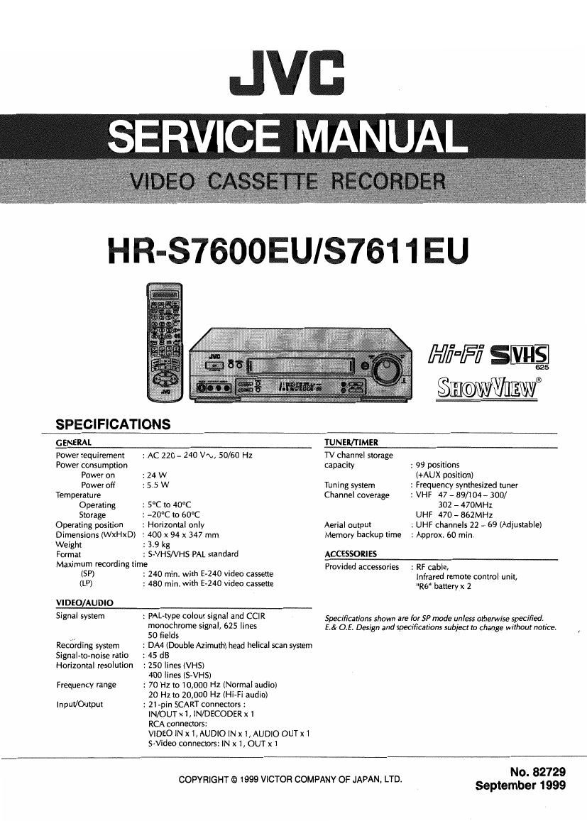
Jvc HRS 7600 Service Manual

This is the 122 pages manual for Jvc HRS 7600 Service Manual.
Read or download the pdf for free. If you want to contribute, please mail your pdfs to info@audioservicemanuals.com.

Page: 1 / 122
left right
Jvc HRS 7600 Service Manual

Extracted text from Jvc HRS 7600 Service Manual (Ocr-read)


Page 1

JVI:
SERVICE MANUAL

HR-S7600EUIS761 1 EU

Hi'fi" SVHS

625

$IIJ©WWHEIIII®

SPECIFICATIONS
GENERAL TUNER/TIMER
Power requirement 2 AC 220 - 240 Vm, 50/60 Hz TV channel storage
Power consumption capacity : 99 positions
Power on : 24 W (+AUX position)
Power off : 5.5 W Tuning system : Frequency synthesized tuner
Temperature Channel coverage 2 VHF 47 - 89/104 - 300/
Operating : 5°C to 40°C 302 - 470MHz
Storage : -20°C to 60°C UHF 470 - 862MHz

Operating position
Dimensions (WxHxD)
Weight

Format

: Horizontal only

:400x 94 x 347 mm

: 3.9 kg

: S-VHS/VHS PAL standard

Maximum recording time

(SP)
(LP)

VIDEO/AUDIO
Signal system

Recording system
Signal-to-noise ratio
Horizontal resolution
Frequency range

Input/Output

: 240 min. with E-240 video cassette
: 480 min. with E-240 video cassette

: PAL-type colour signal and CCIR
monochrome signal, 625 lines
50 fields

: DA4 (Double Azimuth) head helical scan system

: 45 dB
2 250 lines (VHS)
400 lines (S-VHS)
: 70 Hz to 10,000 Hz (Normal audio)
20 Hz to 20,000 Hz (Hi-Fi audio)
: 21-pin SCART connectors :
lN/OUT x1,lN/DECODER x1
RCA connectors:

VIDEO IN x1, AUDIO IN x 1, AUDIO OUT x1

S-Wdeo connectors: IN x 1, OUT xi

Aerial output
Memory backup time

ACCESSORIES
Provided accessories

2 UHF channels 22 - 69 (Adjustable)
: Approx. 60 min.

: RF cable,

infrared remote control unit,
"R6" battery x 2

Specifications shown are for SP mode unless otherwise specified.
E.& of. Design and specifications subject to change without notice.

COPYRIGHT © 1999 VICTOR COMPANY OF JAPAN, LTD.

No. 82729
September 1999

Page 2

TABLE OF CONTENTS

Section Title Page
Important Safety Precautions
INSTRUCTIONS

1. DISASSEMBLV
1.1 DISASSEMBLY FLOW CHART .
1.2 HOW TO READ THE DISASSEM
1.3 DISASSEMBLY/ASSEMBLY METHOD
1.4 SERVICE POSITION ............................
1.4.1 How to take out the Mechanism and Main board
assemblies ................................................................. 1
1.4.2 Precautions for cassette loading in the
"SERVICE POSITION" ................................................. 1-5
1.4.3 Cassette loading and ejection methods in the
"SERVICE POSITION"(See Fig. 143). .
1.5 MECHANISM SERVICE MODE ..............
1.5.1 How to set the "MECHANISM SERVICE MODE"
1.6 EMERGENCY DISPLAY FUNCTION .................
.6 1 How to display record of an emergency faults
1. 6. 2 Detail of emergency faults
1. 6.3 How to clear emergency rec ..
1. 7 SYSCON CIRCUIT ........................
1.
1

7 1 Syscon CPU pin function (IC300 /
.7 2 Syscon CPU pin function (IC3001I 2/2 ..
2. MECHANISM ADJUSTMENT
2. BEFORE STARTING REPAIR AND ADJUSTMENT


.1. 1 Precautions ..............................................
.1. 2 Checking for Proper Mechanical Operations
.13 Manually Removing the Cassette Tape.
..1 4

..1

SewwwwmA-looowwm meow-x-IA-I

Jigs and Tools Required for Adjustment
5 Maintenance and Inspection
2REPLACEMENT OF MAJOR PAR
2.1 Before Starting Disassembling (Pha
between mechanical parts) ..............................
How to Set the Mechanism Assembling Mode
Cassette Holder Assembly
Pinch Roller Arm Assembly..
Guide Arm Assembly and Press Lever Assembly
Audio Control Head
Loading Motor
Capstan Motor
Pole Base Assembly (supply or take-up side) ..
Rotary Encoder
Clutch Unit .......
Change Lever Assemb
Link Lever ......................................................
Cassette Gear, Control Cam and Worm Gear
Control Plate ..................................................
Loading Arm Gear (supply or take-up side) and
Loading Arm Gear Shaft ........................................ 2-15

NNNr'vNNN

2.

....,'\,,I\,N

NNNNNNVIQNNNNN
Adaaddddddda

_.'_._.'_.;._._\r.pm'\i'min4>mio

mm1>QN-IO


17 Take~up Lever, Take-up Head and Control Plate Guide . 216
18 Capstan Brake Assembly ............. 2
19 Sub Brake Assembly (take-up side) .
20 Main Brake Assembly (take-up side), Reel Disk

(take- -up side) and Main Brake Assembly (supply side). 217
21 Tension Brake Assembly, Reel Disk (supply side)

and Tension Arm Assembly ...... -18
22 Idler Lever, IdlerArm Assembly . 2-18
23 Stator Assembly . 2-18
24
2

Rotor Assembly.
5 Upper Drum Assem

2. COMPATIBILITY ADJUSTME

NNNN N NNwNNNN N) NNNN yNMNNNNMNNNNMNN NNNNNNN;'

..2
.2
2.
2.
..2
.2
..2
.2
.2
.2
.2
2.
2
..2
..2
2
.2
.2
2.
..2
..2
.2
2.
2.
.3
.3
3.
3.
.3
.3
3

1 Checking/Adjustment of FM Wave orm Linearity 2-20
2 Checking/Adjustment of the Height and Tlt of the

Audio Control Head .................................................. 2-22
3 Checking/Adjustment of the Audio Control Head

Phase (X- Value) ......................................................... 2-22
4 Checking/Adjustment of the Standard Tracking Preset. 2-23
5 Checking/Adjustment of the Tension Pole 2.-23
6 Adjustment of the Tension Stud.
7 Main Brake Torque Adjustment.

Section Title Page

3. ELECTRICAL ADJUSTMENT
3.1 PRECAUTION ...................
1 Required test equipment .
2 Required adjustment tools ..

.3 Colour bar signal,colour bar pattern
SERVO CIRCUIT ........
.1 PB switching point
.2 Slow tracking preset
V DEO CIRCUIT.


1.
1.
1
3.

wwwcfimmw

3.

QN&N_._._._.

1 EEYIeveI
2 SP/LP REC c
3 PB Y level lS-VHS/VHSI
4 S-VHS VIDEO EO ..
5
6
7

diiaiado

D/A level .........

Pilot burst level ..

Auto picture.
UADIO CIRCUIT
1 REC FM level
SYSCON CIRCUIT ..
.1 Timer clock .....
ON SCREEN CIRCUIT
.1 Character position

01671

3.
3.
3.
3.
3
3.
3
4

IO>OJO>

3.
3.
3.
2
3.
3.
3
3.
3.
3.
3.
3
3.
3
3.4
3
35
3.
3.6
36

wwwwwwwmuwwwm

\iirxixr

4. CHARTS AND DIAGRAMS
NOTES OF SCHEMATIC DIAGRAM ..
CIRCUIT BOARD NOTES ................
4.1 BOARD INTERCONNECTIONS
4.2 VIDEO/N.AUDIO SCHEMATIC DIAGRAM
4.3 ON SCREEN SCHEMATIC DIAGRAM
FMA SCHEMATIC DIAGRAM ............
SYSTEM CONTROL SCHEMATIC DIA
SWITCHING REGULATOR SCHEMATIC DIAG
TUNER SCHEMATIC DIAGRAM
C. BOX CTL SCHEMATIC DIAGRAM
TERMINALIMAIN) SCHEMATIC DIAGRAM
0 MAIN, A/C HEAD AND LOADING MOTOR CIRCUI I' BOARDS. 4-23
1 3D SVHSlVIDEO) SCHEMATIC DIAGRAM . "
2 3D SVHSiBD/TBC) SCHEMATIC DIAGRAM
. 3 3D SVHS CIRCUIT BOARD ..............
. 4 TERMINAL SCHEMATIC DIAGRAM
. 5 TERMINAL CIRCUIT BOARD...
. 6 DEMODULATOR SCHEMATIC D .
4.17 DEMODULATOR CIRCUIT BOARD ............
4.18 SWITCH/DISPLAY, REC SAFETY, JACK AN

du_4;;;mmg¢ms

4
4
4
4
4
4
4
4
4
4
4
4
4

JOG SCHEMATIC DIAGRAMS .................................... 4-41
4.19 SWITCH/DISPLAY, REC SAFETY, JACK AND
JOG CIRCUIT BOARDS .............................................. 4-43

4.20 FDP GRID ASSIGNMENT AND ANODE CONNECTION .. 445
4.21 REMOTE CONTROL SCHEMATIC DIAGRAM ..
4.22 VOLTAGE CHARTS ..............................

4.23 SYSTEM CONTROL BLOCK DIAGRAM .
4.24 VIDEO BLOCK DIAGRAM ..
4.25 AUDIO BLOCK DIAGRAM.


5. PARTS LIST
5.1 PACKING AND ACCESSORY ASSEMBLY
5.2 CABINET AND CHASSIS ASSEMBLY .
5.3 MECHANISM ASSEMBLY ..
5.4 ELECTRICAL PARTS LIST
MAIN BOARD ASSEMBLY <03> .
3D SVHS BOARD ASSEMBLY <05>
TERMINAL BOARD ASSEMBLY <06>
AUDIO CONTROL HEAD BOARD ASSEMBLY <12> .
DEMOD BOARD ASSEMBLY <14>
SW/DISPLAY BOARD ASSEMBLY <28
REC SAFETY BOARD ASSEMBLY <32>
JACK BOARD ASSEMBLY <36> ..
JOG BOARD ASSEMBLY <37>
LOADING MOTOR BOARD ASSEMBLY <55> .

The following table Ilsts the differing point between Models (HR-STGOOEU and HR-s7611EU) In this series.

HFI-S7600EU

HR-87611EU

COSMETIC (FRONT PANEL) CHAMPAGNE

BLACK

Page 9

Fig. 14-2

(8) Place the Switch/Display board assembly, REC safety
board assembly and Jack board assembly on the front
side of the Mechanism and Main board assemblies which
was removed at the step (6), then connect the flat wires
into CN3011 and CN7504 of the Main board assembly
and CN7192 of the Jack board assembly (Refer to Fig.
1-4»3.)


TERMINAL

JACK BOARD
ASSEMBLV

MAIN BOARD
ASSEMBLY

REC SAFETY BOARD
ASSEMBLY
SWITCH/DISPLAY BOARD ASSEMBLY

Fig. 1-4-3

(9) Connect the power cord to the wall socket, and lift the
cassette holder.
(Before turning on the power make sure that there is
nothing which may produce a short circuit, such as faulty
soldering.)

Note: When carrying out diagnosis and repair of the Main
board assembly in the service position, be sure to
ground both the Main board and the Mechanism as-
semblies.

if they are improperly grounded, there may be noise
on the playback picture or the FDP counter display
may move even when the mechanism is kept in an
inoperative status.

1.4.2 Precautions for cassette loading in the "SERVICE
POSITION

The REC safety board assembly detects cassette loading as
well as cassette tabs. Therefore, after the assembly has been
removed in the "SERVICE POSITION", it is requtred to set
the switch manually on the REC safety board assembly when
a cassette is loaded.

1.4.3 Cassette loading and eiection methods in the
"SERVICE POSITION(See Fig. 1-4-3).

(1) Insert a cassette halfway in the Cassette holder assem-
bly.

(2) Set the switch on the REC safety board assembly to ON
(by pressing the switch).

(3) As soon as the cassette starts to be loaded, set the
switch on the REC safety board assembly to OFF (by re-
leasing the switch).

(4) Now the desired operation (recording, playback, fast for-
ward, rewind, etc.) is possible in this status (the status
shown in Fig.1-4-3).

NOTES: 0 When performing diagnostics of the tape play-
back or the recording condition in the "SER V-
ICE POSITIO enter the desired mode be-
fore turning the set upside down, and do not
change the mode when performing diagnos-
tics while the set is placed upside down. lf you
want to switch the mode, turn the set to the
normal position (the status shown in Fig. 1-4-
3).

in the "SERVICE POSITION, the cassette
tabs cannot be detected and recording be-
comes possible even with a cassette with bro-
ken tabs such as the alignment tape. Be very

careful not to erase important tapes. '

(5) The switch on the REC safety board assembly does not
have to be operated when ejecting a tape. But be sure
to turn the set to the normal position before ejecting the
tape,