Jvc HRS 5800 E Service Manual

This is the 18 pages manual for Jvc HRS 5800 E Service Manual.
Read or download the pdf for free. If you want to contribute, please mail your pdfs to info@audioservicemanuals.com.

Page: 1 / 18
left right
Jvc HRS 5800 E Service Manual

Extracted text from Jvc HRS 5800 E Service Manual (Ocr-read)


Page 1

SECTlON 2
ELECTRICAL ADJUSTMENTS

2.1 PREPARATION

Electrical adjustments are required after replacing circuit
components and certain mechanical parts.

It is important to perform these adjustments only after all
repairs and replacements have been completed. Also, do not
attempt these adjustments unless the proper equipment is
available.

2.1.1

. Color television or monitor

Oscilloscope: wide-band, dual-trace, triggered delayed
sweep

Frequency counter

Vectorscope

Audio oscillatOr

Audio voltmeter

Digital voltmeter

Signal generator: RF/ IF sweep/marker

Signal generator: PAL color bar, stairstep, video sweeper

Signal generator: Audio multiplex TV signal generator

11. Recording tape

12. Alignment tape: NIH-2, MH'ZL, MH~2H

13. RCA-S adapter: PTU93001A

14. Presetting unit: PTU94008

15. Head resonance adapter : PTU94007B

16. Adjust coil : PTU94004A

Required test equipment

M-o

d
9595.9999

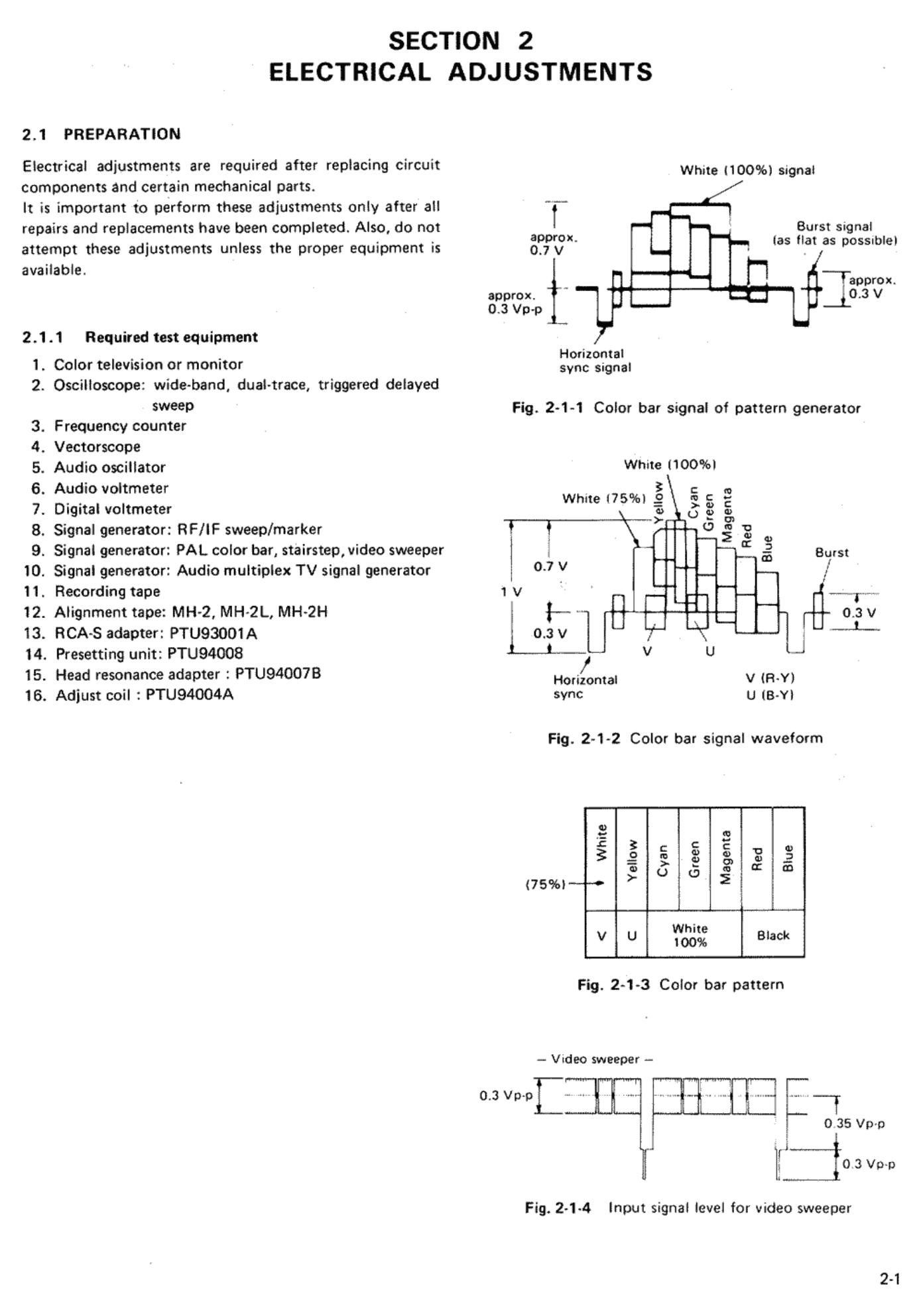
White (100%) signal

Burst signal

approx. las flat as possublel

0.7 V

1 approx.
approx. 0.3 V

0.3 vap

Horizontal
sync signal

Fig. 2-1-1 Color bar signal of pattern generat0r

White 00%|
s
White 175%) g 53 E
\ g u 2 g,
T l , 0 s 5 .
-< 3
I ('5 Burst
0.7 v I!
1 v ' 'm
l t . U a;
U . . V
0.3 V I; i
LL- v U J
Horizontal V (FLY)
sync U lB-Yl

Fig. 2-1-2 Color bar signal waveform

0
3: N
.c g c "
3 g E g E, 8 3
:3 o o g m 3
<75%l~--~°
v u W63; Black

Fig. 2-1-3 Color bar pattern

- Video sweeper -

0.3 Vp.p I .. . ....

O 35 Vp-p

. Il
H [i 0 3 VD~D

Input signal level for video sweeper

Fig. 24-4

2-1

Page 2

2.1.2 Check and adjustment steps

The check and adjustment steps are provided in the follow
ing in the form of charts. For clarity, the nomenclature
used in the charts is outlined below.

No.

ltem

Check Point

Adjustment
Parts

Signal
&
Mode

Color bars
Stairstep
1 kHz
MH-2
color bars
MH-2
stairstep
MH-2

1 kHz
MH-2

RF sweep

MHo2L
color bars

MH-2L
stairstep

MH-2L
RF sweep

MH-2H
color bars

MH-F2
Stairstep

NIH-F2
1 kHz

2-2

Checks and adjustments are numbered in
the recommended sequence in which they
are to be performed.

Name assigned to the particular check and
adjustment step.

Location to which measuring instrument
(oscilloscope unless otherwise noted) is to
be connected.

Variable component (resistor, capacitor,
etc.) to be adjusted in this step. Dash (-j
indicates check only.

0 Input signal required to perform adjust-
ment. Dash (-l indicates that special
signal is not required.

0 Equipment operating mode at time of
check or adjustment.

Color bars signal as video input.
Stairstep signal as video input.
1 kHz sinewave as audio input signal.

Color bars segment of MH-2 alignment
tape.

Stairstep segment of MH-2 alignment tape.

1 kHz audio signal segment of MH-2 align-

ment tape.

RF sweep segment of MH-2 alignment
tape.

Color bars segment of MH-2L alignment
tape.

Stairstep segment of MH-2L alignment
tape.

RF sweep segment of MH-2L alignment
tape.

Color bars segment of NIH-2H alignment
tape.
Stairstep segment of MH-F2 alignment
tape.

1 kHz FM audio signal segment of MH-FZ
alignment tape.

E-E

REC

PB
SEARCH
SLOW
STILL

A DUB
SP mode
EP mode
LP mode

S-VHS mode

VHS mode

Description

Power on and machine in Stop mode.
Recording mode

Playback mode

Search (FWDS and REVS) playback mode
Slow motion playback mode

Pause during playback mode

Audio dubbing mode

SP recording speed

EP recording speed

LP recording speed

Super-VHS recording mode

VHS recording mode

This column provides an explanation of
the step, notes and adjustment values.