Jvc HRJ 268 EE Service Manual

This is the 94 pages manual for Jvc HRJ 268 EE Service Manual.
Read or download the pdf for free. If you want to contribute, please mail your pdfs to info@audioservicemanuals.com.

Page: 1 / 94
left right
Jvc HRJ 268 EE Service Manual

Extracted text from Jvc HRJ 268 EE Service Manual (Ocr-read)


Page 1

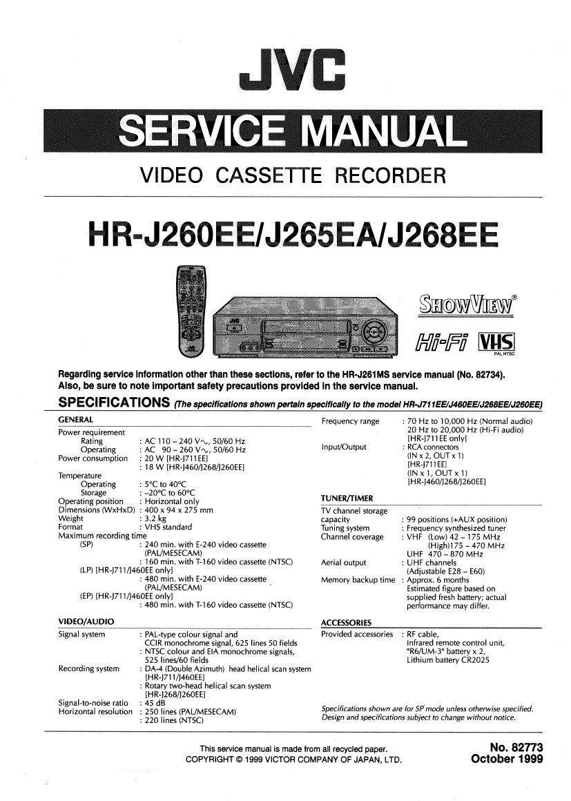
SERVICE MANUAL

VIDEO CASSETTE RECORDER

HR-J260EE/J265EA/J268EE

0%an
Hi=Fi ES

PAL mac

Regarding service Information other than these sections, refer to the HR-J261Ms service manual (No. 82734).
Also, be sure to note important safety precautions provided in the service manual.

S P ECI FICATIONS (The specifications shown pertain specifically to the model HR-J71 155/J46055/J268EE/J260EE)

GENERAL
Power requirement

Rating : AC 110 - 240 V'\., 50/60 Hz

Operating : AC 90 ~ 260 V/\,, 50/60 Hz
Power consumption : 20 W [HR-J7ii EEI

: 18 W [HR-J460/1268/J260EE]

Temperature

Operating : 5°C to 40°C

Storage : -20°C to 60°C

Operating position

: Horizontal only

Dimensions (WxHxD) : 400 x 94 x 275 mm

Weight
Format

: 3.2 kg
: VHS standard

Maximum recording time

(SP)

2 240 min. with E-240 video cassette
(PAL/MESECAM)
2 160 min. with T-l 60 video cassette (NTSC)

(LP) [HR-J71 I/J460EE only]

: 480 min. with E-240 video cassette
(PAUMESECAM) '

(EP) [HR-J71 l/J460EE only]

VIDEO/AU DIO

: 480 min. with T-160 video cassette (NTSC)

: 70 Hz to 10,000 Hz (Normal audio)
20 HZ to 20,000 Hz (Hi-Fl audio)
[HR-1711 EE only]

Frequency range

Input/Output : RCA connectors
(IN x 2, OUTx i)
[HR-J71IEE]
(INX l,OUTx 1)
[HR-J460/1268/J260EE]
TUNER/TIMER
TV channel storage
capacity : 99 positions (+AUX position)

: Frequency synthesized tuner
: VHF (Low) 42 - 175 MHz
(Hith 75 - 470 MHZ

UHF 470 - 870 MHZ

: UHF channels
(Adjustable E28 - E60)

: Approx. 6 months
Estimated figure based on
supplied fresh battery; actual
performance may differ.

Tuning system
Channel coverage

Aerial output

Memory backup time

ACCESSO RI ES

Signal system

Recording system

Signal~to~noise ratio
Horizontal resolution

: PAL-type colour signal and
CCIR monochrome signal, 625 lines 50 fields

2 NTSC colour and ElA monochrome signals,
525 lines/60 fields

: DA-4 (Double Azimuth) head helical scan system
[HR-J711/J46OEE]

: Rotary two-head helical scan system
[HR-J268/J26OEE]

: 45 dB

: 250 lines (PAL/MESECAM)

: 220 lines (NTSC)

Provided accessories : RF cable,
Infrared remote control unit,
"Rb/UM-B" battery x 2,

Lithium battery CR2025

Specifications shown are for SPmode unless otherwise specified.
Design and specifications subject to change without notice.

This service manual is made from all recycled paper.
COPYRIGHT © 1999 VICTOR COMPANY OF JAPAN. LTD.

No. 82773
October 1999

Page 27

This unit is provided with a mechanism assembly mode. It
is therefore necessary to enter this mode for assembling and
disassembling procedures.

This mode is usually not in use, manually set it when it is
required.

2.2.2 How to Set the Mechanism Assembling Mode
Remove the mechanism assembly and place it bottom side
up. (See SECTION 1 DISASSEMBLY.) Turn the worm gear
toward the front so that the guide hole of the control cam is
brought into alignment with the hole at the mechanism as
sembly chassis. This position renders the mechanism assem-
bling mode operational. Make sure that the control plate is
located in alignment with the mark E. (See Fig.2-2v1.)


Chassis hole
Worm gear

Control plate

2.2.3 Cassette Holder Assembly

1. How to remove

(1) Remove the guide rail and roller cam assembly. (See
Fig.2v2-2.)
(3 lugs on the guide rail and one lug on the roller cam
assemblyl

Roller cam
assembly LUQ

U

Fig. 22-2

(2) Remove the two slit washers and remove the cassette
housing bracket. (See Fig.2-2-3.)

(3) Remove the opener guide, spring(A), door opener, relay
gear and limit gear. (See Fig.2-2-3.)

Relay gear

Door opener Slit washers

Cassette housing bracket

Fig. 2-2-1

Fig. 2-2-3

Page 31

2.2.7 Loading Motor

1. How to remove

(1) Remove the belt wound around the worm gear.

(2) Open the two lugs of the motor guide and remove the
loading motor, loading motor board assembly and motor
guide altogether by pulling them up.

(3) When replacing the loading motor board assembly, take
care with the orientation of the loading motor. (install so
that the loading motor label faces upward.)

(4) When the motor pulley has been replaced, choose the
fitting dimension as indicated in Fig.2»2-16,

oadlng motor board assembly


Loading motor

Motor guide

T1- 6.5 i 0.2 mm
Motor pulley

Worm gear

Belt

Fig. 2-2-1 6

2.2.8 Capstan Motor

1. How to remove

(1) Remove the belt (capstan) on the mechanism assembly
back side.

(2) Remove the three screws (A) and remove the capstan
motor.

Screws(A)

E? ?\Sorew(A)
VJ» J.
with

Capstan motor

Fig. 2-2-17

2. How to install (Centering the mounting position)
When the capstan motor has once been removed and then
reinstalled out of the initial correct position in the rotational
direction, the capstan motor current may be unstable dur-
ing operation in high or low temperatures) This may result
in greater Wow & Flutter and occasionally in power break-
down because of current over - load. Install the capstan mo-
tor while following the procedure given below.

(The capstan motor is centrally located when the unit is
shipped from the factory.)

(1) Provisionally tighten the three screws (A) securing the
capstan motor,

(2) Install the mechanism assembly to which the capstan
motor is provisionally fastened on the bottom chassis
which incorporates the Main board assembly. (No need
to tighten the screws for mounting the mechanism.)
Make sure that all the connectors for the mechanism as-
sembly and the Main board assembly are correctly in-
stalled as indicated in Fig. 2-2-18.

Fig. 2-2-1 8

(3) Making sure that the connector CN3003 of the capstan
motor is correctly mounted, and securely tighten the
three screws (A).

Note: When the capstan motor has been re-
placed with a new one, perform record-
ing in the EP mode for at least 2 min-
utes at normal temperatures immedi-
ately before starting the FF/REW or
SEARCH operations (Aging).

2-11