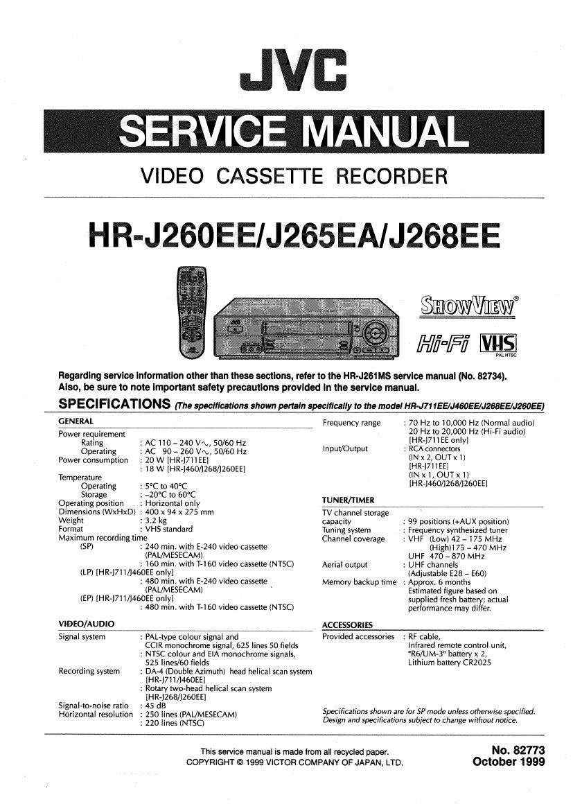
Jvc HRJ 265 EA Service Manual

This is the 94 pages manual for Jvc HRJ 265 EA Service Manual.
Read or download the pdf for free. If you want to contribute, please mail your pdfs to info@audioservicemanuals.com.

Page: 1 / 94
left right
Jvc HRJ 265 EA Service Manual

Extracted text from Jvc HRJ 265 EA Service Manual (Ocr-read)


Page 1

SERVICE MANUAL

VIDEO CASSETTE RECORDER

HR-J260EE/J265EA/J268EE

0%an
Hi=Fi ES

PAL mac

Regarding service Information other than these sections, refer to the HR-J261Ms service manual (No. 82734).
Also, be sure to note important safety precautions provided in the service manual.

S P ECI FICATIONS (The specifications shown pertain specifically to the model HR-J71 155/J46055/J268EE/J260EE)

GENERAL
Power requirement

Rating : AC 110 - 240 V'\., 50/60 Hz

Operating : AC 90 ~ 260 V/\,, 50/60 Hz
Power consumption : 20 W [HR-J7ii EEI

: 18 W [HR-J460/1268/J260EE]

Temperature

Operating : 5°C to 40°C

Storage : -20°C to 60°C

Operating position

: Horizontal only

Dimensions (WxHxD) : 400 x 94 x 275 mm

Weight
Format

: 3.2 kg
: VHS standard

Maximum recording time

(SP)

2 240 min. with E-240 video cassette
(PAL/MESECAM)
2 160 min. with T-l 60 video cassette (NTSC)

(LP) [HR-J71 I/J460EE only]

: 480 min. with E-240 video cassette
(PAUMESECAM) '

(EP) [HR-J71 l/J460EE only]

VIDEO/AU DIO

: 480 min. with T-160 video cassette (NTSC)

: 70 Hz to 10,000 Hz (Normal audio)
20 HZ to 20,000 Hz (Hi-Fl audio)
[HR-1711 EE only]

Frequency range

Input/Output : RCA connectors
(IN x 2, OUTx i)
[HR-J71IEE]
(INX l,OUTx 1)
[HR-J460/1268/J260EE]
TUNER/TIMER
TV channel storage
capacity : 99 positions (+AUX position)

: Frequency synthesized tuner
: VHF (Low) 42 - 175 MHz
(Hith 75 - 470 MHZ

UHF 470 - 870 MHZ

: UHF channels
(Adjustable E28 - E60)

: Approx. 6 months
Estimated figure based on
supplied fresh battery; actual
performance may differ.

Tuning system
Channel coverage

Aerial output

Memory backup time

ACCESSO RI ES

Signal system

Recording system

Signal~to~noise ratio
Horizontal resolution

: PAL-type colour signal and
CCIR monochrome signal, 625 lines 50 fields

2 NTSC colour and ElA monochrome signals,
525 lines/60 fields

: DA-4 (Double Azimuth) head helical scan system
[HR-J711/J46OEE]

: Rotary two-head helical scan system
[HR-J268/J26OEE]

: 45 dB

: 250 lines (PAL/MESECAM)

: 220 lines (NTSC)

Provided accessories : RF cable,
Infrared remote control unit,
"Rb/UM-B" battery x 2,

Lithium battery CR2025

Specifications shown are for SPmode unless otherwise specified.
Design and specifications subject to change without notice.

This service manual is made from all recycled paper.
COPYRIGHT © 1999 VICTOR COMPANY OF JAPAN. LTD.

No. 82773
October 1999

Page 13

SECTION 1
DISASSEMBLY

1.1 DISASSEMBLY FLOW CHART

This flowchart lists the disassemblmg steps for the cabinet
parts and RC. boards in order to gain access to itemls)
to be serviced. When reassembling, perform the stepls) in
reverse order. Bend, route and dress the flat cables as they
were originally laid.

® [:m Top cover

w Bracket?
770m panel assemblym
E DRUM assembrnyj

E-Mechanism as§§lfl§ij
l

E Main board assemblymj

@@©@®

1.2 HOW TO READ THE DISASSEMBLY AND ASSEMBLY

STEP FIG
/Loc PART NAME NO' POINT NOTE
NO. -
(D TOP COVER D1 3(31)
® BRACKET DZ 2(82)
(3) FRONT PANEL D3 7(L1)
ASSEMBLY
® DRUM ASSEMBLY o4 3(53), Iin.
CNIIWRII.
CNIIWHZ).
CLEANER
ASSEMBLY
C5) MECHANISM DS 2(s4I.2ISBI.2IL3i,
ASSEMBLY CN1(WR3) © MAIN BOARD Do (56). 6(L4)
ASSEMBLY
(1) (2) (a) (4) (5)

(1) Order of steps in Procedure

When reassembling, perform the stools) in the reverse

order. These numbers are also used as the identification

(location) N0. of parts Figures.

(2) Part name to be removed or installed.

(3) Fig.No. showing procedure or part location

(4) Identification of part to be removed,unhooked,unlocked,
released,unpluged,unclamped or unsoldered. P = Spring,

W = Washer, S = Screw, L = Locking tab, CNxx(WRxx) = Re-

move the wire (WRxx) from the connector (CNXX).

NOTE: The bracketed ( ) WFI' o! the connector symbol
are assigned nos. in priority order and do not cor-
respond to those on the spare parts list.

(5) Adjustment information for installation

1.3 DISASSEMBLYIASSEMBLY METHOD
STEP FIG
/Loc PART NAME No POINT NOTE
NO. -
® TOPCOVER o1 3(51)
® BRACKET oz 2(52)
(3] FRONTPANEL D3 7(L1l
ASSEMBLY
@ DRUMASSEMBLY o4 3(S3l,(L2),
CNIIWRII,
cmtwnz).
CLEANER
ASSEMBLY
© MECHANISM Ds 2(SA),2(SS),2(L3),
ASSEMBLY CNI (WR3)
@ MAIN BOARD D6 ($6).6(L4)
ASSEMBLY

When reattaching the Front panel assembly, make sure that
the door opener @ of the Cassette holder assembly is low
ered in position prior to the reinstallation.

When reattaching the Front panel assembly, pay careful at-
tention to the switch lever not to make it touch the switch
knob © of the Main board assembly from the side.

(If the switch knob of the Man board assembly is damaged,
cassette loading is impossible.)


When inserting the flat wire into the connector, be careful
not to make a mistake in the positioning of its electrodes.

- When it is required to remove the screws (84) retaining
the Mechanism assembly, please refer to the "Procedures
for Lowering the Cassette holder assembly". (See on pages
1-3.)

. When removing the Mechanism assembly only, unhook
the two spacers connecting it with the Main board as-
sembly with pliers from the back side of the Main board
assembly first, and then remove the Mechanism assem-
bly.

' When reattaching the Mechanism assembly to the Main
board assembly, take care not to damage the sensors on
the Main board. (D3001: LED, 03002: Start sensor, 03003:
End sensor)

1-I