Jvc HRD 520 EE Service Manual

This is the 64 pages manual for Jvc HRD 520 EE Service Manual.
Read or download the pdf for free. If you want to contribute, please mail your pdfs to info@audioservicemanuals.com.

Page: 1 / 64
left right
Jvc HRD 520 EE Service Manual

Extracted text from Jvc HRD 520 EE Service Manual (Ocr-read)


Page 1

__ m > .
High Olfi
DIGI IAL
, TRACKING
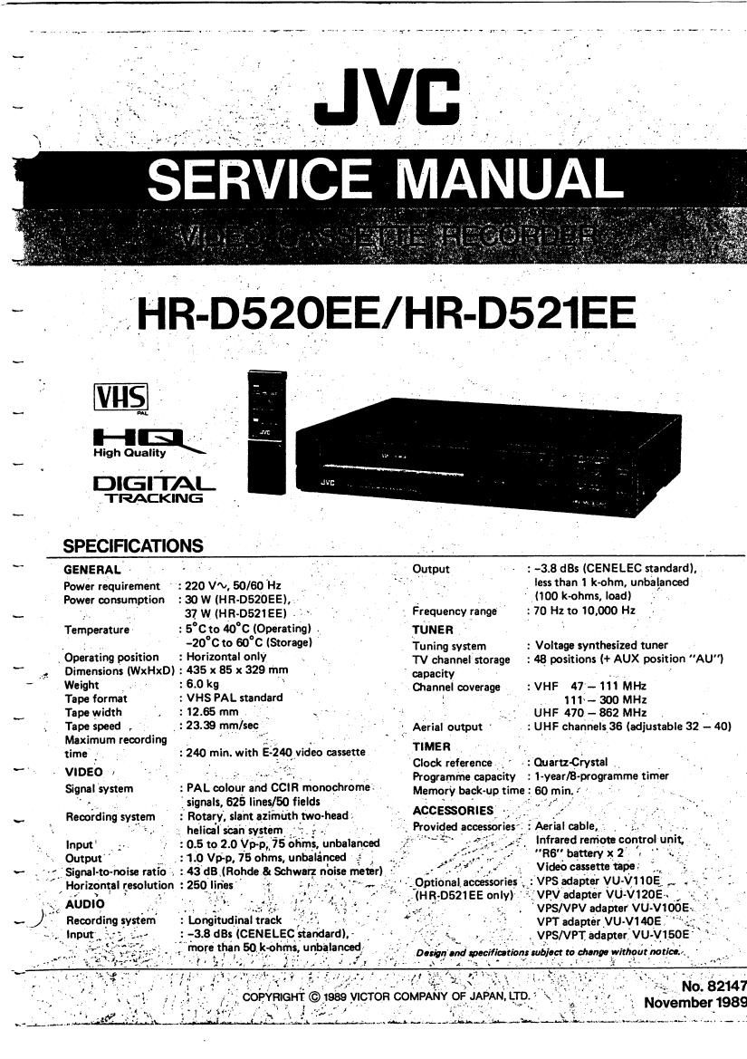
SPECIFICATIONS . .
v GENERAL ' , V . V Output » : ~38 st (CENELEC standard).
Power requirement : 220 V'v, 50/60 'Hz 1 . less than 1 kohm, unbalanced
Power consumption :30W (HR-052056, v , 7 " V (100 k~ohms, load)
._ _, ' 37 w -13.052155, g, ., . ' , Frequency range ' _: 70 Hz to 10,000 Hz
Temperature : 5°C oto 40°C°l096ratingi , TUNER V '
- » . . _ '2°_ Cto 50 c7 (Storage) V Tuning system : Voltage synthesized tuner
~ OperatIng posmon : Honzontal °"'V _ ' TV channel storage : 48 positions (+ AUX position "AU)
" V, Dimensions (WxHxD): 435 x 85 x 329 mm - capacity - ' . V p -
Wefl' . ~ ' =5- 0 k9 _ I ChanneI coverage : VHF 41- 111 MHz
Tape format . : VHS PAL standard 1 "1 _ 300 MHz
v Tape width , : 12.65 mm _ or ~ ' s , UHF 470.. 862 MHz .
Tape 59" r . 23-39 INF/59° ,, " Aerial output ' : UHF channels 36 (adjustable 32- 40)
Maximum recording ' ",5- - '*
time .' _ : 240 min. with E- 40 video cassette TIMER , , .
..- VIDEO _ » - - jg , Clock reference , ' - : Quartz-Crystal
V ' ' ' ' ' " " - ~. , , Programme capacity : 1 year/8-programme timer
Signal system : PAL colour and CClR monochrome? Memory back-up time 60 min
" _ i'signals, 625 lines/50 fields _ ' ~ ' , \
v Recording system : Rotary, slant azimuth two-head iv ACCESSORIES. i . ' ' "
7 ' ; helical sun system _; . - Proviqed accessories Aerial cable, . , , ' - '
Input : 0.5 to 2.0 Vp-p, 75 ohms, unbalanced ' ' . Infrared remote EOMIqIUDIi. -,_,
Output J14) Vp-p, 75 ohms, unbalanced , . ' RB" battery X. 2 ' , *-
.- : 43 dB (Rohde & Schwarz noise meter) Video 9 up.

' AUDIO

' Signal-to-noise ratio I

' Horizontalresolution :250_|nes '1


'VPS adapter VU V110E,.

VPV adapter VU- V120E . >

'VPS/VPV adapter VU- V100

VPT adapter VU-VMOE "
, VPS/VPTadapter VU-V150E , ~

Croptional, acoessoriés
(H3705215E only)


£7.0-

':' Longitudinal track

Recording system
.lnput

Page 2

NOTE: For a technical description, please refer to Technical Guide VT682036 HR-DSZO PAL.

0 The instructions shown pertain specifically to the Model HR-D520EE. For detailed descriptions, be sure to
consult the Instruction booklets of HR-DEZI EE.

0 The following table lists the differing points between models (suffixes HR-DSZOEE and HR-D521EE).

HR-DSZOEE HR-D521EE
LCD No Yes
Remote Control unit
VPS/VPV/VPT No Yes
Connector .

TABLE OF CONTENTS

Section Title Page Section Title Pogo
3 .8 AUDIO BLOCK DIAGRAM 3-15

Important Safety Precautions

3 . 9 SYSTEM CONTROL BLOCK DIAGRAM . 3-17
INSTRUCTIONS 3 .10 VIDEO UNIT AND VIDEO (MAIN) SCHEMATIC
1. MECHANISM ADJUSTMENTS DIAGRAM 3-19
1 .1 PRECAUTIONS .............................................................. 1.1 3.11 VIDEO UNIT CIRCUIT BOARD 3-21
1 .2 CHECK WITHOUT CASSETTE HOUSING 3 . 12 SERVO SCHEMATIC DIAGRAM 3-23
I .3 MANUALLY REMOVING CASSETTE TAPE 3.13 AUDIO SCHEMATIC DIAGRAM . 325
1 . 4 TEST EOUIPMENTS .......... . .............................. 3 .14 SYSTEM CONTROL SCHEMATIC DIAGRAM ...... .. 3-27
1 . 5 DISASSEMBLY ., 3.15 DECK TERMINAL. MODE MOTOR, CAPSTAN MDA,
1 5 . 1 Top my" 2 C. HOUSING SCHEMATIC DIAGRAMS ................ 3-29
1 ,5 , 2 Front panel mummy , 2 3 . 16 DECK TERMINAL, MODE MOTOR, C. HOUSING,
1 .5 . 3 Bottom cover 2 A/C HEAD CIRCUIT BOARD , 330
1 ,5 . 4 Cassette housing 2 3 . 17 MAIN CIRCUIT BOARD 3.31
1 .5 . 5 Cassette housing door 2 3.18 PRE/REC SCHEMATIC DIAGRAM 3.33
1 .6 MAIN MECHANISM PARTS .. , 3 3 .19 PRE/REC CIRCUIT BOARD 3-35
1 .7 INSPECTION AND MAINTENANCE ............................. l -5 3 .20 IFITUNER CTL SCHEMATIC DIAGRAM 3-37
1 . 7 . 1 Standard servicing schdule for main 3 .21 IF/TUNER CTL CIRCUIT BOARDS ........................ .. 3-39
wmpomnts . 3 . 22 TlMER/DISPLAY/SWITCH SCHEMATIC DIAGRAM .. 3-41
1 .3 MAIN PARTS REMOVAL AND REPLACEMENT . 3 .23 TlMER/DISPLAYISWITCH CIRCUIT BOARD .............. 3-43
3.24 POWER TRANSFORMER AND REGULATOR (MAIN)
2. ELECTRICAL ADJUSTMENTS SCHEMATIC DIAGRAMS .............................................. 3-45
2. 1 PREPARATION ............................................................. 2 .1 3 . 25 POWER TRANSFORMER CIRCUIT BOARD ................ 3-47
2 . 1 . 1 Required test equipment . , 2 .1 3.26 REMOTE CONTROL SCHEMATIC DIAGRAM
2 .1 .2 Check and adiustmem steps . 2 - 2 IHRvDS20EEI ................................................................. 3-49
2 , 2 TIMER CIRCUIT 2 .3 3 . 27 REMOTE CONTROL SCHEMATIC DIAGRAM
2 .3 SERVO CIRCUIT .. 2 - 3 (HR-0521 EE) ...........................................
2 _ 4 VIDEO CIRCUIT 2 . 4 3.28 FIF CONVERTER SCHEMATIC DIAGRAM
2 .5 AUDIO CIRCUIT .. 2-5
2 . 6 TUNER/IF CIRCUI 2 _ 5 4. EXPLODED VIEWS AND PARTS LIST
6.1 PACKING ASSEMBLY
3' CHARTS AND DIAGRAMS 4 . 2 CABINET ASSEMBLY
3.1 CIRCUIT BOARD AND LOCATION . . 4 ' 3 395 ASSEMBLY
4 . 4 MECHANISM ASSEMBLYI1I

3 .2 GENERAL INFORMATION
.2 . 1 Connections .................
Disconnecting the flatwire

5. ELECTRICAL PARTS LIST
POWER TRANSFORMER BOARD ASSEMBLY <01> ........... 5 -
MAIN BOARD ASSEMBLY <03> ...........
VIDEO UNIT BOARD ASSEMBLY (05>
IF BOARD ASSEMBLY <07) ..........................
Semiconductors ........... TUNER CONTROL BOARD ASSEMBLY <08)
. 7 Replacement of chip parts . AUDIO CONTROL HEAD BOARD <12 > ........
3 . 3 MAIN TYPES OF ACTIVE AND PACKAGE TlMER/DISPLAY/SW BOARD ASSY <21 >
CIRCUITS UPPER DRUM BOARD < 41>
BOARD INTERCONNECTIONS . PRE/REC AMP BOARD ASSEMBLY <43> .....
VIDEO BLOCK DIAGRAM DECK TERMINAL BOARD ASSEMBLY <51>

PREIREC BLOCK DIAGRAM LOADING MDA BOARD ASSEMBLY <55)
SERVO BLOCK DIAGRAM CASSETTE HOUSING BOARD <56>

Indications ...................


Schematic diagram values
Signal flow in the schematic

uuuuuuu
NNNuNN
mmbwu
uuwuuuuuu
uuuNNNMN

uuuu
401015

Page 22

No.

Vltem

Checkpoints

Adjustment and Checks

Tension arm assembly
Tension band assembly , w.

0m 1.5m}

..:

Tension arm any

Fig. we

Tension pole position

.- See Fig. 1-8-8.

(Effect: poorrFM waveform
response)

1

1) Remove the cassette housing assembly and
set the mechanism for the playback mode
,.,(see 1.2).
2) Turn the eccentric adjust pin to align the tip
of the tension arm with the edge of the main
.rdeck. '

Back tension
(Effect: skew)

I) When the tension pole position is correctly
, adjusted, the back tension will assume the
correct value.

2) Use the Back Tension Casette Gauge and
set for the playback mode. Confirm reading
of 22 to 35.

3) Changing the tension pole position in order
to vary the back tension will cause adverse
effects elsewhere.

Pinch roller cam

Control cam

Half loading gear assembly
Guide arm assembly

Spring each other
Guide arm asy \

Holes overlm
each othert

Hall loading
gear any

Set mechanism to Eject mode position.

Important: Do not remove or
disturb parts other than
those mentioned.

See Fig. 1-8«9.

, each other.
G o
/

Holes confront

Pinch roller cam

oles overlap

9

O

/ Control cam

Fig. use

1) When installing the pinch roller cam, overlap
the largest hole of the gear portion with the
hole of the deck.

2) Set the control cam on the deck with the
hole of the groove overlapped with the hole
of the deck. Observe that the small hole of
the control cam and the ridge of the pinch
roller cam are aligned.

(If the control cam does not fit readily, shift
the rear plate assembly within the range of
play.)

3) Install the half loading gear assembly with
the hole overlapped with the hole of the
deck. Secure with E-ring.

4) Install the guide assembly over the spring
and with the hole overlapping that of the
deck. Engage the spring correctly.

Cassette housing asembly

Install the cassette housing assembly with the
mechanism in the Eject mode. Also observe
that the inner holder of the housing is raised
and locked.

1-8