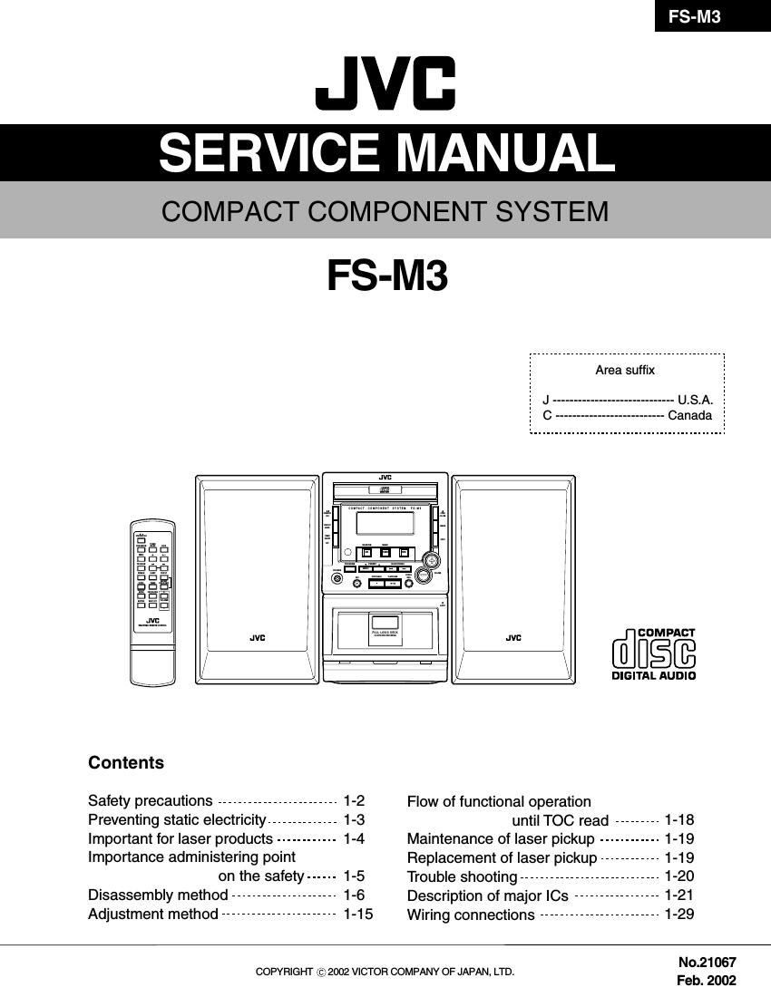
Jvc FSM 3 Service Manual

This is the 49 pages manual for Jvc FSM 3 Service Manual.
Read or download the pdf for free. If you want to contribute, please mail your pdfs to info@audioservicemanuals.com.

Page: 1 / 49
left right
Jvc FSM 3 Service Manual

Extracted text from Jvc FSM 3 Service Manual (Ocr-read)


Page 1

FS-M3 1-2 1. This design of this product contains special hardware and many circuits and components specially for safety purposes. For continued protection, no changes should be made to the original design unless authorized in writing by the manufacturer. Replacement parts must be identical to those used in the original circuits. Services should be performed by qualified personnel only. 2. Alterations of the design or circuitry of the product should not be made. Any design alterations of the product should not be made. Any design alterations or additions will void the manufacturer`s warranty and will further relieve the manufacture of responsibility for personal injury or property damage resulting therefrom. 3. Many electrical and mechanical parts in the products have special safety-related characteristics. These characteristics are often not evident from visual inspection nor can the protection afforded by them necessarily be obtained by using replacement components rated for higher voltage, wattage, etc. Replacement parts which have these special safety characteristics are identified in the Parts List of Service Manual. Electrical components having such features are identified by shading on the schematics and by ( ) on the Parts List in the Service Manual. The use of a substitute replacement which does not have the same safety characteristics as the recommended replacement parts shown in the Parts List of Service Manual may create shock, fire, or other hazards. 4. The leads in the products are routed and dressed with ties, clamps, tubings, barriers and the like to be separated from live parts, high temperature parts, moving parts and/or sharp edges for the prevention of electric shock and fire hazard. When service is required, the original lead routing and dress should be observed, and it should be confirmed that they have been returned to normal, after re-assembling. 5. Leakage currnet check (Electrical shock hazard testing) After re-assembling the product, always perform an isolation check on the exposed metal parts of the product (antenna terminals, knobs, metal cabinet, screw heads, headphone jack, control shafts, etc.) to be sure the product is safe to operate without danger of electrical shock. Do not use a line isolation transformer during this check. Plug the AC line cord directly into the AC outlet. Using a "Leakage Current Tester", measure the leakage current from each exposed metal parts of the cabinet, particularly any exposed metal part having a return path to the chassis, to a known good earth ground. Any leakage current must not exceed 0.5mA AC (r.m.s.). Alternate check method Plug the AC line cord directly into the AC outlet. Use an AC voltmeter having, 1,000 ohms per volt or more sensitivity in the following manner. Connect a 1,500 10W resistor paralleled by a 0.15 F AC-type capacitor between an exposed metal part and a known good earth ground. Measure the AC voltage across the resistor with the AC voltmeter. Move the resistor connection to each exposed metal part, particularly any exposed metal part having a return path to the chassis, and meausre the AC voltage across the resistor. Now, reverse the plug in the AC outlet and repeat each measurement. Voltage measured any must not exceed 0.75 V AC (r.m.s.). This corresponds to 0.5 mA AC (r.m.s.). 1. This equipment has been designed and manufactured to meet international safety standards. 2. It is the legal responsibility of the repairer to ensure that these safety standards are maintained. 3. Repairs must be made in accordance with the relevant safety standards. 4. It is essential that safety critical components are replaced by approved parts. 5. If mains voltage selector is provided, check setting for local voltage. Good earth groundPlace this probe on each exposed metal part. AC VOLTMETER (Having 1000 ohms/volts, or more sensitivity) 1500 10W 0.15 F AC TYPE ! Burrs formed during molding may be left over on some parts of the chassis. Therefore, pay attention to such burrs in the case of preforming repair of this system. In regard with component parts appearing on the silk-screen printed side (parts side) of the PWB diagrams, the parts that are printed over with black such as the resistor ( ), diode ( ) and ICP ( ) or identified by the " " mark nearby are critical for safety. (This regulation does not correspond to J and C version.)

Page 2

FS-M3 1-3 Short land CD pickup unit Connector Conductive material (conductive sheet) or iron plate (caption) Anti-static wrist strap 5. Attention when traverse unit is decomposed *Please refer to "Disassembly method" in the text for the CD pickup unit. Apply solder to the short land before the card wire is disconnected from the connector on the CD pickup unit. (If the card wire is disconnected without applying solder, the CD pickup may be destroyed by static electricity.) In the assembly, be sure to remove solder from the short land after connecting the card wire. Electrostatic discharge (ESD), which occurs when static electricity stored in the body, fabric, etc. is discharged, can destroy the laser diode in the traverse unit (optical pickup). Take care to prevent this when performing repairs. Preventing static electricity 1. Grounding to prevent damage by static electricity Static electricity in the work area can destroy the optical pickup (laser diode) in devices such as CD players. Be careful to use proper grounding in the area where repairs are being performed. 2. About the earth processing for the destruction prevention by static electricity Ground the workbench by laying conductive material (such as a conductive sheet) or an iron plate over it before placing the traverse unit (optical pickup) on it. 2-1 Ground the workbench 2-2 Ground yourself Use an anti-static wrist strap to release any static electricity built up in your body. In order to maintain quality during transport and before installation, both sides of the laser diode on the replacement optical pickup are shorted. After replacement, return the shorted parts to their original condition. (Refer to the text.) Do not use a tester to check the condition of the laser diode in the optical pickup. The tester's internal power source can easily destroy the laser diode. 3. Handling the optical pickup 1. 2. Do not subject the traverse unit (optical pickup) to strong shocks, as it is a sensitive, complex unit. Remove solder of the short land on the card wire after replacing the optical pickup. For specific details, refer to the replacement procedure in the text. Remove the anti-static pin when replacing the traverse unit. Be careful not to take too long a time when attaching it to the connector. Handle the card wire carefully as it may break when subjected to strong force. It is not possible to adjust the semi-fixed resistor that adjusts the laser power. Do not turn it. 4. Handling the traverse unit (optical pickup) 1. 2. 3. 4.

Page 23

FS-M3 1-24 AN7312 (IC202) : Dual recording/Playback pre-amplifier circuit with ALC 1. Terminal layout 3. Pin function2. Block diagram 17 Pin No.Symbol I/OFunction ~ 14 8 ~ GND ALC time constant ALC input Ch.1 Output Ch.1 Phase compensation Ch.1 N.E.B. Ch.1 Input Ch.1 Input Ch.2 N.E.B. Ch.2 Phase compensation Ch.2 Output Ch.2 ALC input Ch.2 Ripple filter Vcc 1 2 3 4 5 6 7 8 9 10 11 12 13 14- - I O - I I I I - O I - -GND ALC time constant by resistance and capacitor Right channel ALC input Right channel output No connect Right channel negative feed back input Right channel signal input Left channel signal input Left channel negative feed back input No connect Left channel output Left channel ALC input Ripple filter Power supply 14 13 12 11 10 9 1 2 3 4 5 6 Ripple Filter Amp. Ch2 8 ALC 7 GNDVcc Amp. Ch1 BA4558N (IC402) : Dual operational amplifier 1. Terminal layout & Block diagram 1ch 2ch 1 234 56 78 OUT1 -IN1 +IN1 V EE +IN2 -IN2 OUT2 Vcc 2. Pin function 1 2 3 4 5 6 7 8 OUT1 -IN1 +IN1 V EE+IN2 -IN2 OUT2 Vcc A output A - input A + input V- B + input B - input B output V+ PIN No. Symbol O I I - I I O - I/O Function LA4282 (IC401) : Power amplifier 1. Terminal layout & Block diagram 1 234NF1 IN1 RIPPLE FILTER PRE GND IN2 6 789NF2 OUT2 MUTE POWER GND2 Vcc 11 CH1 CH2 Vcc 510 12 Ripple filter Thermal over voltage protector Mute circuit 300 30k 30k 300 2. Pin function 1 2 3 4 5 6 7 8 9 10 11 12 NF1 IN1 RIPPLE FILTER PRE GND IN2 NF2 OUT2 MUTE POWER GND2 Vcc OUT1 POWER GND1 Right channel negative feed back Right channel signal input Ripple filter PRE GND Left channel signal input Left channel negative feed back Left channel output Mute control Power GND Power supply Right channel output Power GND PIN No. Symbol - I - - I - O - - - O - I/O Function OUT1 POWER GND1

Page 35

FS-M3 3-6 Item Parts number Parts name Ar ea Electrical parts list (Main board) Remarks Block No. 01 A C326 OW06-50475-02 E.CAPACITOR 4.7MF 50V C327 OW06-50475-02 E.CAPACITOR 4.7MF 50V C328 OW05-02103-10 MYLAR CAPACITOR 0.01MF 10% C329 OW05-02103-10 MYLAR CAPACITOR 0.01MF 10% C330 OW06-16227-02 E.CAPACITOR 220MF 16V C331 OW05-00104-00 C.CAPACITOR 0.1MF 10% 50V C332 OW06-16337-02 E.CAPACITOR 330MF 16V C334 OW06-16227-02 E.CAPACITOR 220MF 16V C335 OW05-00223-00 C.CAPACITOR 0.022MF 10% 50V C336 OW06-16476-02 E.CAPACITOR 47MF 16V C341 OW06-16107-02 E.CAPACITOR 100MF 16V C342 OW05-00104-00 C.CAPACITOR 0.1MF 10% 50V C343 OW06-25107-00T E.CAPACITOR 100MF 25V C344 OW06-25228-00 E.CAPACITOR 2200MF 25V C401 OW06-50225-02 E.CAPACITOR 2.2MF 50V C402 OW06-50225-02 E.CAPACITOR 2.2MF 50V C403 OW05-00331-00 C.CAPACITOR 330PF C404 OW05-00331-00 C.CAPACITOR 330PF C405 OW06-16106-02 E.CAPACITOR 10MF 16V C406 OW06-50225-02 E.CAPACITOR 2.2MF 50V C407 OW06-50225-02 E.CAPACITOR 2.2MF 50V C408 OW06-25107-00T E.CAPACITOR 100MF 25V C409 OW06-25107-00T E.CAPACITOR 100MF 25V C410 OW05-02104-10 MYLAR CAPACITOR 0.1MF 10% C411 OW05-02104-10 MYLAR CAPACITOR 0.1MF 10% C412 OW06-25108-00 E.CAPACITOR 1000MF 25V C413 OW06-25108-00 E.CAPACITOR 1000MF 25V C414 OW06-50107-02 E.CAPACITOR 100MF 50V C415 OW06-50228-00 E.CAPACITOR A 2200MF 20% 50V C416 OW05-07104-00 C.CAPACITOR 0.1MF 50V C417 OW06-16107-02 E.CAPACITOR 100MF 16V C420 OW06-50225-02 E.CAPACITOR 2.2MF 50V C421 OW06-50225-02 E.CAPACITOR 2.2MF 50V C422 OW06-16476-02 E.CAPACITOR 47MF 16V C423 OW05-00101-06 C.CAPACITOR 100PF 5% C424 OW05-00101-06 C.CAPACITOR 100PF 5% C425 OW05-00101-06 C.CAPACITOR 100PF 5% C426 OW05-00101-06 C.CAPACITOR 100PF 5% C427 OW06-16476-02 E.CAPACITOR 47MF 16V C428 OW06-16476-02 E.CAPACITOR 47MF 16V C429 OW06-16227-02 E.CAPACITOR 220MF 16V C430 OW06-16227-02 E.CAPACITOR 220MF 16V C431 OW05-00223-00 C.CAPACITOR 0.022MF 10% 50V C432 OW06-35227-00 E.CAPACITOR 220MF 35V C433 OW05-00101-06 C.CAPACITOR 100PF 5% C434 OW05-00101-06 C.CAPACITOR 100PF 5% C435 OW06-35107-00 E.CAPACITOR 100MF 35V C451 OW05-00104-00 C.CAPACITOR 0.1MF 10% 50V C452 OW05-00104-00 C.CAPACITOR 0.1MF 10% 50V C453 OW05-00104-00 C.CAPACITOR 0.1MF 10% 50V D101 OW02-00348-00TUNING DIODE SVC348-S D103 OW02-00201-00TUNING DIODE SVC201SPA D104 OW02-00201-00TUNING DIODE SVC201SPA D105 OW02-04148-00RDIODE 1N4148 D108 OW02-04148-00RDIODE 1N4148 D109 OW02-04148-00RDIODE 1N4148 D110 OW02-04148-00RDIODE 1N4148 D111 OW02-04148-00RDIODE 1N4148 D201 OW02-04148-00RDIODE 1N4148 D202 OW02-04148-00RDIODE 1N4148 D301 OW02-04148-00RDIODE 1N4148 D302 OW02-04148-00RDIODE 1N4148 D303 OW02-04148-00RDIODE 1N4148 D401 OW02-04148-00RDIODE 1N4148 D402 OW02-04148-00RDIODE 1N4148 FMANT OW29-00003-00 FM ANT WIRE 26UL-1007 BLK. IC101 OW03-02104-01 IC TA2104BN IC102 OW03-09257-01 IC TC9257F IC201 OW03-01330-00 IC UPC1330HA IC202 OW03-07312-00 IC AN7312 IC301 OW03-09422-00 IC TC9422F IC302 OW03-07812-00 IC A NJM7812A IC401 OW03-04282-00 IC A LA4282 IC402 OW03-04558-03 IC BA4558N LL105 OW81-10001-00CUSHION 10X10X10MM L101 OW08-01014-02 IFT 1A1014N 10MM L102 OW08-45635-00 AM ANT COIL MRHNF-45635GG L105 OW09-45045-00 FM COIL D4.5X4.5T 0.8MM L106 OW09-02750-05 FM OSC.COIL 2422 549 43772 L107 OW09-70101-00INDUCTOR 10MH L108 OW09-70101-00INDUCTOR 10MH L201 OW09-40474-00WCHOKE COIL 47MH D6X8MM L202 OW09-40474-00WCHOKE COIL 47MH D6X8MM L203 OW08-07163-00 BIAS OSC COIL 7LIA63N LIK HANG Q113 OW01-00945-16 TRANSISTOR 2SC945P Q114 OW01-00945-16 TRANSISTOR 2SC945P Q115 OW01-00945-16 TRANSISTOR 2SC945P Q117 OW01-00733-16 TRANSISTOR 2SA733P Q118 OW01-00945-16 TRANSISTOR 2SC945P Q119 OW01-09018-07 TRANSISTOR 9018G Q121 OW01-00945-16 TRANSISTOR 2SC945P Q122 OW01-00945-16 TRANSISTOR 2SC945P Q123 OW01-00945-16 TRANSISTOR 2SC945P Q124 OW01-00945-16 TRANSISTOR 2SC945P Q201 OW01-08050-04S TRANSISTOR 8050D Q202 OW01-00945-16 TRANSISTOR 2SC945P Q203 OW01-00945-16 TRANSISTOR 2SC945P Q204 OW01-00945-16 TRANSISTOR 2SC945P Q205 OW01-00945-16 TRANSISTOR 2SC945P Q206 OW01-08050-04S TRANSISTOR 8050D Q207 OW01-00945-16 TRANSISTOR 2SC945P Q208 OW01-00945-16 TRANSISTOR 2SC945P Q209 OW01-00945-16 TRANSISTOR 2SC945P Q210 OW01-00945-16 TRANSISTOR 2SC945P Q211 OW01-00733-16 TRANSISTOR 2SA733P Q212 OW01-00945-16 TRANSISTOR 2SC945P Q213 OW01-00945-16 TRANSISTOR 2SC945P Q214 OW01-00945-16 TRANSISTOR 2SC945P Q215 OW01-00945-16 TRANSISTOR 2SC945P Q301 OW01-00945-16 TRANSISTOR 2SC945P Q302 OW01-00945-16 TRANSISTOR 2SC945P Q303 OW01-01383-18 TRANSISTOR 2SC1383R Q304 OW01-00945-16 TRANSISTOR 2SC945P Q305 OW01-01240-00 TRANSISTOR A 2SB1240 Q Q401 OW01-08050-04S TRANSISTOR 8050D Q402 OW01-08050-04S TRANSISTOR 8050D Q403 OW01-00733-16 TRANSISTOR 2SA733P Q404 OW01-08050-04S TRANSISTOR 8050D Q405 OW01-08050-04S TRANSISTOR 8050D Q406 OW01-08050-04S TRANSISTOR 8050D Q409 OW01-00945-16 TRANSISTOR 2SC945P R102 OW07-15104-50T CARBON RESISTOR 100K 1/8W 5% R103 OW07-15104-50T CARBON RESISTOR 100K 1/8W 5% R121 OW07-15473-50T CARBON RESISTOR 47K 1/8W 5% R122 OW07-15473-50T CARBON RESISTOR 47K 1/8W 5% R123 OW07-15202-50T CARBON RESISTOR 2K 1/8W 5% Item Parts number Parts name Ar ea Remarks A