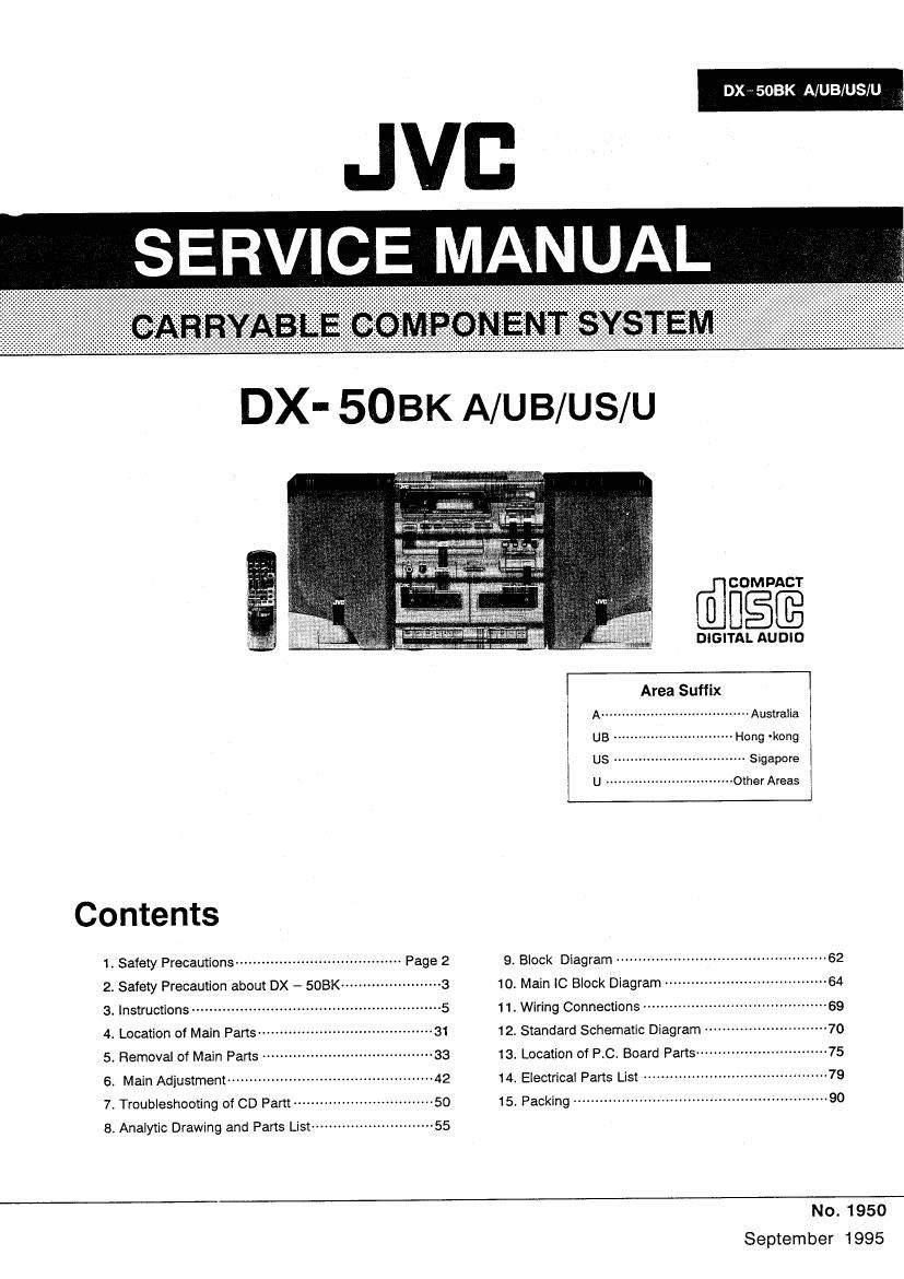
Jvc DX 50 BK Service Manual

This is the 108 pages manual for Jvc DX 50 BK Service Manual.
Read or download the pdf for free. If you want to contribute, please mail your pdfs to info@audioservicemanuals.com.

Page: 1 / 108
left right
Jvc DX 50 BK Service Manual

Extracted text from Jvc DX 50 BK Service Manual (Ocr-read)


Page 1

DXV 508K A/UB/US/U

JVB
SERVICE MANUAL

Contents

mumwt-uN-t

, Safety Precautions ...................................... Page 2
. Safety Precaution about DX - SOBK ----------------------- 3
. Instruotlons ......................................................... 5
Location of Main Part5 ....................................... 31
. Removal of Main Pans

. Main Adjustment -----------------------------

. Troubleshooting of CD Pam ------------------------------- so
. Analytic Drawing and Parts List --------------------------- 55

@figfi

DIGITAL AUDIO

Area Suffix
Australia

U3 Hong -kong
us ................................ Sigapore
U ............................... Other Areas
9. Block Diagram ................................................ 62
10. Main IC Block Diagram ..................................... 64
11. Wiring Connections ........................

12. Standard Schematic Diagram .

13. Location of P.C. Board Parts -----
14 Electrical Parts List .......................................... 79
15. Packing .......................................................... 90

No. 1950
September 1995

Page 2

ox - 503K A/UB/US/U l

1. Safety Precautions

..

.The design this product contains special hardware and many circuits and components specially for safety purposes. For continued
protection. no changes should be made to the original design unless authorized in writing by the manufacturer, Replacement parts must
be identical to those used in the original circuits. Service should be performed by qualified personnel only,

2. Alterations of the design or circuitry of the product should not be made. Any design alterations of the product should not be made. Any
design alterations or additions will void the manufacture's warranty and will further relieve the manufacture of responsibility for personal
injury or property damage resulting therefrom.

3. Many electrical and mechanical parts in the product have special safety- related characteristics. These characteristics are often not
evident from visual inspection norcan the protection afforded by them necessarily be obtained by using replacement components rated
for higher voltage, wattage. etc. Replacement parts which have these special safety characteristics are identified in the parts list of
service manual. Electrical components having such features are identified by ( A )on the schematic diagram and parts list in the
service manual. The use of a substitute replacement which does not have the same safety characteristics as the recommended
replacement part shown in the para list of service manual may create shock. fire. or other hazards.

4. The leads in the products are routed and dressed with ties, clamps , tubings, barriers and the like to be separated from live parts, high
temperature parts. mpving parts and or sharp edges for the prevention of electric shock and fire hazard. When service is required. the
original lead routing and dress should be observed. and it should be confirmed that they have been returned to normal, after
reassembling.

5. Leakage current check (Electrical shock hazard testing)

After re- assembling the product, always perform an isolation check on the exposed metal parts of the product (antenna terminals,

knobs. metal cabinet, screw heads. headphone jack, control shafts. etc.) to be sure the product is safe to operate without danger of

electrical shock. Do not use a line isolation transformer during this check.

~ Plug the AC line cord directly into the AC outlet. using aLeakage current tester". measure the leakage current from each exposed
metal part of the cabinet. particulary any exposed metal part having a return path to the chassis, to a known good earth ground. Any
leakage current must not exposeed 0.5mA AC(r.m.s.)

- Alternate check method

. . . . A t AC VOLTMETER
Plug the AC line cord directly Into the AC outlet Use an C voltme er m (Having 1000 ohmilvolt,
having 1,000 ohms per volt or more sensitivity in the following manner. or more sensitivity.)
Connect a 1,500 ohms 10W resistor paralleled by a 0.15 ,0. F AC type '- kl
capacitor between an exposed metal part and a known good earth 0.15uF AC TYPE
ground. Measure the AC voltage across the resistor with the AC L

Float this probe
voltmeter. Move the resistor connection to each exposed metal part. on each expend

1500 n to W metal part.

particularly any exposed metal part having a return path to the chassis.
and measure the AC voltage across the resistor. Now, reverse the plug 600d earth around
in the AC outlet and repeat each measurement. Any voltage measured

Warning (Singapore only)

1. This equipment has been designed and manufactured to meet international safety standards.

2. It is the legal responsibility of the repairer to ensure that these safety standards are maintaintaind.
3. Repairs must be made in accordance with the relevant safety standards.

4. It is essential that safety critical components are replaced by approved parts.

5. If mains voltage selector is provided, check setting for local voltage.

2 (No. 1950)

Page 10

DX - 503K A/UB/US/U

NAMES 0F PARTS AND THEIR NOMBRE DE LAS PARTES V SUS s L
C FUNCTIONS FUNCIONES fi$I¢mgm ARIJJIIE
CD playeleenaral section WNW do cDIseccién genoul comm/m9

0 POWER union

0 SENSOR seclion
Tne remote corrIrol Sign) is reoeived In In SENSOR
section When the POWER bullon is Set Io STANDBY
with AC power supplied, llIumIMagIc OOMPU PLAV is
activated by approaching mis moon with your hand,

0 Panel STANDBV micanr

o ACTIVE HYPER-BASS button and Manor

0 LIVE SURROUND Mon

0 Preset equalizer (PRESET Eo. (CLEAR/BEATIPOPD
buttons

0 DispIay window

Repeai pIay indicator

RANDOM play Irocaror

PROGRAM rrrooe macaw

UVE SURROUND indcatcx

FRESET ED. Indcalors

FuncfioanIack runner Iisplay

Play time display

0 DISPLAY ounon
Use lo uLspIay mo cuvenl time.

0 VOLUME bulimia
.: Use In increase ma Volume.
-: Use In muse me Volllne.
(oomroi lame Irom VOL o no VOL 50,)

63996999

fimi

gm mum vaw

1:! I_l I_I I I I _
_I I I
no


801611 POWER
Seccion SENSOR
La senal de comm remmo es recioloa en la
secclon SENSOR, Cuando Se COIoca el Down
POWER en STANDBY can aiimentaclorl US CA. 56
acllva IIIumiMagic OOMPU PLAY 3] aploxlmar Ia
mm a esta sechOn,
IndIcadov STANDBY de alimentacion
BDIOn e Indicadol ACTIVE HYPER-BASS
Balm LIVE SURROUND
Eolones (PRESET EL] (CLEAR/BEAT/PDF) pale
ploglamacion del Ecualizadol
Visa! de indlcamon
§ Indicadov dB Yepelicion dB Veploduccdm
Indicador de vsprcduccion RANDOM
Indicaduv as mode PROGRAM
8 Indicadcu LIVE SURROUND
Indicadmes PRESET E0
® IndicaaOH as IuncIonlnamero d2 pisla
(D Indicaclbn del Irempo de reproduccron
Eotéfl DISPLAY
Ulillcela para Ilamar Ia hora acmal
Batches VOLUME
+ Uiilioelo Date aumeniar el volumen.
A Ulilloelo paIa rsducir e! volumen
(miles de oonllDI de VOL 0 a VOL 50.)

III-
Gil
D

0 AUX Mon
0 CD my
0 MIC Jack
O MIC LEVEL oomol
0 :0 my OPEN/CLOSE (:I Dalton
0 REPEAT play union
6 RANDOM play ouIIon
Memes jack (PHONESI (3.5 mm Iie. sIoIeo mini)
Comm neanpmnes (Impeaanco (5 0 ID I Ln) Io Ihis
jack. Speaker sound aqurrIaxicalIy swrlones on when
the headphones are unnamed.
0 CD operation buttons
Play/pause mu l>nl :
Prmwflayadhcortompierrporariiy.
stoploiear omen (El) :
Press In mop playing a rise or camel programmed
play. This also sou so under
SEARCH-l mm <4, m) :
Press In Iowa mo oogrnnrng oI lungs and to stun
Iomeralreverse search ooemiions.

H

10 (No. 1950)

3010" AUX

Ponadlsco (19 CD

Jack MIC

control MIC LEVEL

80167! (A) OPEN/CLOSE dsl Donadisoo 03 CD

Baton de reproduccién REPEAT

BDIbn de Ieploduocion RANDOM

Jack PHONES para audIIonos (mini estereo 35 mm
as mam.)

Conecte Ios audilonors (Impedancia de 16 Q a 1
kn), a este jack.

Cuando Se Eoneclan IDS audflonos. el Sonido del
allavoz es auwmlicmme sdenciado.

Eatones para operaclon as CD

man (l>ll) do reproduccionlpause:

Presionolo para roproduolr un alsco or para parar
Iempovaliamenle

Eolon (El) 62 parada/boflado:

PIesiOnelc para delensv la Ieploduccidn d6 Un
disco 0 canpelar la Iaproduccion programme. EsIe
Iambién aEIiva El mode de CD,

Bolonos (mi puma SEARCH

Proslonelo para localizal el Inioio de las mllslcas y
para IIIICiolV las operamones Os basqueda hacia
«slants/aims

o iifilfli ( POWER I
O Elfimfit (SENSOR)
Iémémmsmsonfiimgm E32 afiifii
PowakfiifliéfiSTANDBYfi. kaafiififltfiifiiflfl
fimlytcowu PLAYo
O Qifififitfiififi (STANDBY)
0 Efifififififimfiiffi/flfi (ACTIVE HYPER
BASS )
O Militia ( LIVE SURROUND )
ofifiiflifiés Gavan/mm) Iii ( PRESET
EQ. (CLEAR/BEAT/POPI >
0 (EM
® Emir;
@mmgmila ( RANDOM I
© fififilfim ( PROGRAM )
© Minsk/7% (LIVE SURROUND)
(Er) fifiififiifififi (PRESET EQ. )
WEE/mfififi
® magma
0 SEW ( DISPLAY )
mfiéfiffifimo
0 3% (VOLUME)
+: fiififiififiio
7 : mwfififigo
( Emfifilfivm DEVOL 50,, I m

calm (AUX)

O CDfli

I mam (MIC)

O Eflim ( MIC LEVEL )

OchliBH/lfl (A) u (OPEN/CLOSE)

O imam (REPEAT)

0 minimum (RANDOM >

O Em (PHONES) ( 35mm Emmy)
mega (fififiglsnfiim I iithfim if!
E. wwwasamnmn

.vCDIlIEIfl
IKE/Em (I>II) :
fiflfllflflmfifimififio
{$th (Cl) :
figflalflifimflflERflWfifimfis
nmwumcwn.
11m (SEARCH) (m. m):
fimfiflfiflfifiuflfllfiE/Eflflfifiih

Page 52

DX - 503K AIUB/US/U I

I Feed section

Is 42V or 0V produced at

|0601 ® 7 ___.' I0601 is defective.
Check the circuitry in the
Do both ends of the feed . . OK . .
motor produce 2V? $23? of R565, 566 and ICSOZ is defective.
J, Y
Feed motor is defective
Fig. 7-3
I Focus section
Does a pulse waveform
appear at |0601 Q3 ?
5 V
- _ .! |0601 is defective,
; , o v
t-i
24 sec.
i Y
Does a ramp waveform Does a ramp waveform
appear at CN501 <13) ? appear at IC501 7
- - - - - - - - - - - N Check the circuitry in the vicinity
W fZV 2.1V : 1V V OHC501®'@.
I 2 _____L_ ' ' __-- .
. . .
3-1 i-4 i
. .
2.4 sec. 2 4 sec
ICSO1 is defective.
iv iY
pickup is defective_ Check the circuitry in the
vicinity of K3502 ® - @.

52 (No. 1950)

J,OK

I0502 is defective.

Fig. 7-4