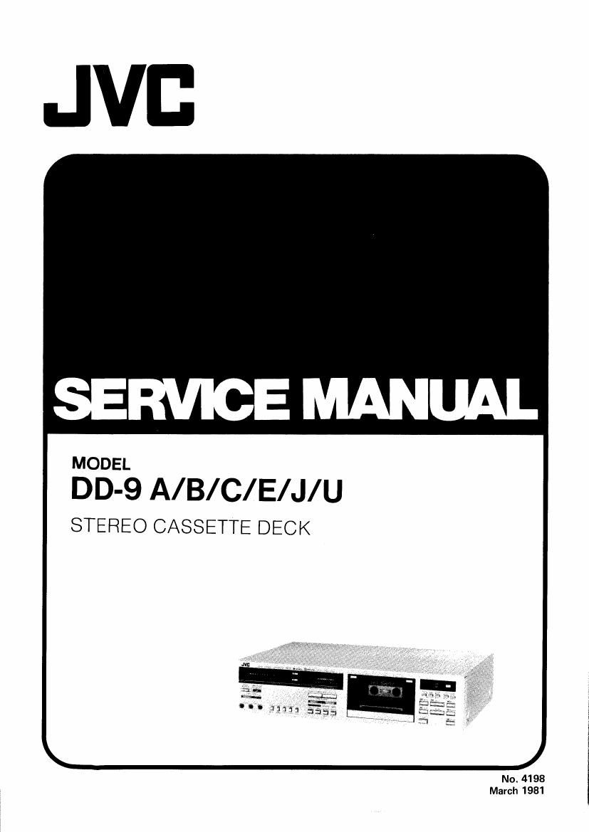
Jvc DD 9 Service Manual

This is the 54 pages manual for Jvc DD 9 Service Manual.
Read or download the pdf for free. If you want to contribute, please mail your pdfs to info@audioservicemanuals.com.

Page: 1 / 54
left right
Jvc DD 9 Service Manual

Extracted text from Jvc DD 9 Service Manual (Ocr-read)


Page 2

DD-QA/B/C/E/J/U

Contents

Page
Features ................................ 2
Specifications ............................ 3
Controls and Connections .................... 4
Main Parts Location ........................ 5
Maintenance ............................. 5
Description on New Technology ................ 6
Removal of the Main Parts .................... 8
Main Adjustments .......................... 9
Block Diagram (1) ........................ 17
Block Diagram (2) ........................ 18
Wiring Connection (1) ...................... 19
Wiring Connection (2) ...................... 20
Wiring Connection (3) ...................... 21
Standard Voltage Value ..................... 22
lntegrant Circuits ......................... 23
Standard Schematic Diagram (Main Amp. Circuit) . . . 25
Standard Schametic Diagram (Computer Circuit) . . . . 26

Standard Schematic Diagram (Mecha, Control Circuit) 27

Features

' 2-motor full-logic mechanism with quartz-locked pulse-

servo D.D. motor
0 A quartz-locked pulse-servo D.D. motor newly
developed for capstan drive and a DC motor for reel
drive
0 Low wow/flutter (W RMS 0019%)
0 TIMER STANDBY mechanism (with maloperation
protection)
0 AUTO-REWIND mechanism
0 Remote control terminal provided (R-50E optional)
I Built»in computer B,E.ST. tuning system for automatic
adjustment of Bias, Equalization and Sensitivity of tape
' Metaltape compatible
I Three-head system permitting monitoring while record-
ing is being made
0 X-cut SA (Sen-Alloy) combination record/playback
head
0 2-933) SA erase head

No. 4198

Page

Standard Schematic Diagram
(Fl Circuit, DD Motor Circuit) .............. 28
Enclosure Assembly and Electrical Parts .......... 29
Mechanical Component Parts ................. 30
Enclosure Assembly and Electrical Parts List ....... 31
Mechanical Component Parts List .............. 34
Main Amp. P.W. Board Parts List ............... 36
Main Amp. P.W. Board Parts .................. 39
Computer P.W. Board Parts .................. 40
Computer P.W. Board Parts List ............... 41
Mecha. Control P.W. Board Parts, Parts List ........ 44
Display P.W. Board Parts, Parts List ............. 46
DD Motor Circuit Parts List .................. 47
Other P.W. Board Parts ..................... 48
Other P.W. Board Parts List .................. 49
Packing, Packing Material Parts List ........ Back cover
Accessories ........................ Back cover

I 2-color FL digital meter (PEAK/VU selectable) with
peak hold function
DC configured record/playback amplifier
Electronic control for recording level adjustment
Equipped with ANRS/DOLBY B and DOLBY C NR
moise reduction systems.

I Timer standby capability for automatic recording or
playback using an AC timer

I Headphones in connection with slide system output
level control

I Record muting (REC MUTE) mechanism (with operation

indicator LED)

New slim design with push button switches

Page 7

Dolby* C-Type Noise Reduction System:
Noise is reduced and MOL increased dramatically.

The Dolby C-type closely resembles the B-type in operation,
the system compatible with ANRS, yet offers even better
performance and more distinctive features. Namely:

I It provides about 20 dB above 1 kHz, and 15 dB even at
500 Hz of noise reduction.

I At 10 kHz (at 0 VU recording), it improves MOL by
4 dB maximum.

I It is immune to undesirable side effects, such as modu-
lation noise and breathing.

I Finally, it is tolerant of noise reduction encode/decode
errors. Level matching is not critical.

(*Dolby isa trademark of Dolby Laboratories, Inc.)

The basis of C-type noise reduction

Dolby C noise reduction solves the problem of achieving
a large amount of compression and expansion without
introducing undesirable side effects by the use of two pro-
cessing stages in series, each supplying 10dB of compression
during recording and of expansion during playback. These
circuits operate at independent levels. One, identified as the
high-level stage in Figure B, is sensitive to signals at about
the same levels as Dolby B-type noise reduction, while the
other, the Iow~level stage, operates on signals of somewhat
lower level. Because the two stages operate in tandem with
each other, their effect is to multiply the signals (or add and
subtract in dBs), so that a total of 20 dB of compression
and expansion,and thus of noise reduction, is accomplished.
Yet simultaneously, at no time is the signal subject to the
vagaries of a single compression or expansion action of
20 dB. In other words, the tandem two-level, two-stage con-
figuration provides a much more accurate control of the
signal than a single compander circuit would be able to
achieve.

Two conventional Dolby 8 IC circuits are used in a modified
way in C-tvpe noise reduction to carry out the two-level,
two-stage scheme. Thus a desirable side benefit of C-type
noise reduction is that it can be executed from the begin
ning with readily available and economical parts (the
development of a dedicated Dolby C integrated circuit in
the future would, however, simplify incorporating C-type
NR in products). Furthermore, one of the two stages can
be easily configured to provide the B-type characteristic at
the push of a switch, so cassette decks incorporating C-tvpe
noise reduction can be economically equipped with Dolby
B NR as well for perfect compatibility with existing B-type
recordings.

V ' I . Improved by ,
all!!! LEV ' about 3 (kHa

Dolhy'C on

'uoise Rediiellon or;

Sm Improved by about
. (rm: and above)

oumui leel (as)

Noise uni * . . . . ,
Noise Reduction or;

, slNlmpraved
abouliSdB
so m 2m 5m icon
Freq-mom

Dolby C Improvement

Other developments

In addition to two-level processing, Dolby C-type noise
reduction incorporates a number of further innovations.
Two of these, shown in Figure B as anti-saturation and
spectral skewing networks, are carefully calculated fre
quency response modifications introduced in the encoding
(record) process and reciprocally compensated for in the
decode (playback) process. Their purpose is two-fold: to
further guard against audible side effects, and to ensure
the practicality of the system in day-to-day consumer use.
The specific benefits of these innovations include the
reduction of encode-decode errors and a reduction of
upper-middle and high frequency tape saturation and its
side effects, such as high frequency losses and inter-
modulation distortion. Together with the two-level, two-
stage configuration, these new developments result in a
20 dB noise reduction system at least as free of side effects
as the 10 dB B-type system, and one which is just as practi-
cal in day-to-day use.

-6-A-

Page 15

DD-QA/B/C/E/J/U

. Adjusting Standard
Step Item Adjustment point value Remarks

4 FL(F|uores- 1. Set the METER switch to VU. VR701, 0 VU Due to parts replacement.
cence Level) 2. Set the MONITOR switch to SOURCE, VR501, -20 VU
indicator then apply a 1 kHz signal of around VR601
sensitivity -20 dB to the R-ch and L-ch of the LINE

IN terminals.

3. Adjust the INPUT LEVEL control so that
the output level at the LINE OUT termi-
nals is -4 dB.

4. Adjust VR701 ("0" dB level adjustment)
so that 0" dB lights at both R and L.

At this time, "0 dB must go out at both
R and L with the input ATT (attenuation)
level lowered by 0.5 dB.

5. Lower the input ATT level by 20 dB.

6. Adjust VR501 (chh) and VR601 (R-ch)
so that "420" dB lights at both R and L.
At this time, "-20" dB must go out at
both R and L with the input ATT level
lowered by I dB.

7. Repeat steps 4.- 6,

5* Encoder 1. Off the Dolby C NR switch. VRA02 -2.5st
(recording) 2. Apply a 400 Hz signal to LINE IN. (331- 802
calibration ance VR set to center, and inpUt level con-

Dolby C trol set to some position.) WE ,N a, c Wm,
adj. 3. Adjust input signal so that TP103 output cha
level becomes #25 st. 30:3

4. Adjust VRA02 and 302 so that TP104 W rem mo,

output level becomes -2.5 st. rm. WA
liifilur

6* LINE IN 1. Balance VR set to center, and input level VRl -4 st
level L-ch control set to max.
and R-ch 2. Adjust input signal so that output level of
deflection L-ch monitor becomes -4 st, and then
adj. adjust VRl so that output level of R-ch

monitor becomes -4 st.

7" Checking Record 1 kHz, 50 Hz and 12.5 kHz signals at For SF/ Reference This checking should be per-
record/ an input level of 0 VU to -20 dB, NORM frequency; formed for normal, chrome and
playback Play back the tape. tape; 1 kHz metal tapes and for both right
frequency Check to see that the 50 Hz and 12.5 kHz VR103, + 3 3" left channels. _
response signal output deviations fail within the stanr For ZSOA/ gtESDdHBz 1' cBalgssefterEgctkasilgalgerenefglla

dard range, using the 1 kHz signal output as Cr02 0 i 3 dB be performed referrigg to m:

a reference. tape; at record/playback frequency

Immense ,,, mgr, mumcles VR108, 12.5 kHz response of a cassette deck

(With a small bias current) 208 depends more greatly upon

5 \N ,7 For Metal the bias current than does

3 / \ {5:391:09 that of an open reel defik. The

a ' -~\ " , current measurin met od de-

S /\l\ opnmum level 209 scribed below in agn alternative

D. .

g; Decrease in high frequencxes one.

a: lwith a larger bias Current) 2. If the bias current is not pro-

50 Hz 1 kHz 125 K2 perly adjusted, the record and

FrEGuencv (H1) playback characteristics be-

come as shown left.

8 Adjusting 1. Apply a 1 kHz, approx. -10 dB signal to VR105, 0 VU The level difference between left
recording the LINE IN terminals. Adjust the record- 205 and right channels for SF/NORM
level ing level controls until the signal is avail- tape,chrome tape and metal tape

able at -4 st at the LlNE OUT termi~
rials.

2, After checking to see if the FL indicator
becomes 0, record the signal applied to
both left and right channels using normal
tape.

3. Play back the recording part. Perform the
recording signal adjustment with VR105
and VFI205 so that the FL indicator be-
comes 0.

should be less than 1 dB ll VU).
Perform the adjustment using a
normal tape, level difference be-
tween recording and playback
for SA/Cr02 and metal tapes,
should be less than 15 dB, and
that between left and right chan-
nels should also be less than IdB.

,13_

No.4198