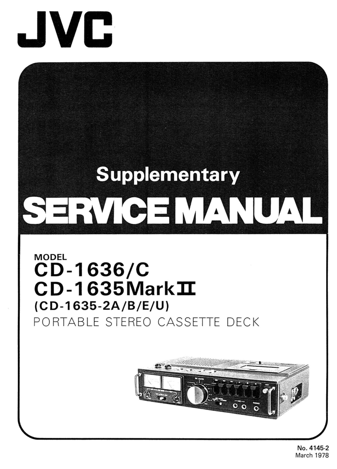
Jvc CD 1635 C Service Manual

This is the 4 pages manual for Jvc CD 1635 C Service Manual.
Read or download the pdf for free. If you want to contribute, please mail your pdfs to info@audioservicemanuals.com.

Page: 1 / 4
left right
Jvc CD 1635 C Service Manual

Extracted text from Jvc CD 1635 C Service Manual (Ocr-read)


Page 2

CD-1636/C

CD-1635Mark II J

Main Adjustments

[I] Equipment and measuring instruments used for adjustment.

Electrical adjustment
1) Electronic voltmeter

2) Audio frequency oscillator
(range; 50-20kHz and output OdB with impedance

60052)
3) Attenuator

4) Standard tapes for REC/PB
Maxell UD - for "NORM" position
TKD SA -- for Cr02" position

5) Reference tapes for playback (JVC Test Tape)
VTT-658 (for head azimuth adj.)
VTT-664 (for Reference level 1kHz)
VTT-675N (for playback frequency response)

6) Resistors

10052 (for measurement of the bias current)
60052 (for attenuator matching)

Audio F req. Osc.

} or equivalent

[II] Electrical circuit adjustment procedure

Adjustment should be performed in the order of steps 1,2,3.

Playback system

Electronic

Attenuator

CD-1 636/ C
CD-1635-2A/B/E/U

Voltmeter, .-
/ -

Step Item Adjustment 235:?" 8323; Remarks
1 Level meter 1. Set the deck in the record mode. R134 VU meter Perform the adjustment when
deflection R234 reading:0 the parts are replaced.

2. Input 1kHz signals to MIC or LINE
IN jacks (with a level of -60st
(0.78mV) approx. for MIC input or
~10st (24QmV) approx. for LINE
IN input.)
Adjust the recording volume controls
so that the voltage across LINE OUT
is ~35st (518mV).

3. Adjust two semi-fixed variable
resistors R1341Loch) R234(R-ch) so
that the level meters indicate zero VU.

2 Play back Adjust R115 and R215 to obtain zero R115 VU meter 1. Adjust reproduction level
level VU meter reading using reference tape R215 reading: 0 when heads are replaced.

VTT-664 (old ref. no. TMT-6009). 2. Make this adjustment after
Set equalizer switch in "NOR MA L" making sure level meter
position and turn off AN RS switch deflection angle is correct.
when adjusting play back level.

3 Checking the Play back the VTT-675N test tape. Standard frequency: The 1kHzoutputwith
playback fre- Check to see if the outputs at the fre~ 1kHz the equalizer switch
quency response quencies conform to the standard "NORM" position; set to NORMALrefers

levels. +2.5dBi3dB at 63Hz to Cr02 position.
OtSdB at 10kHz
"Cr02" position
+2.5dBt3dB at 63Hz
-4.5dBi3dB at 10kHz

No. 41452