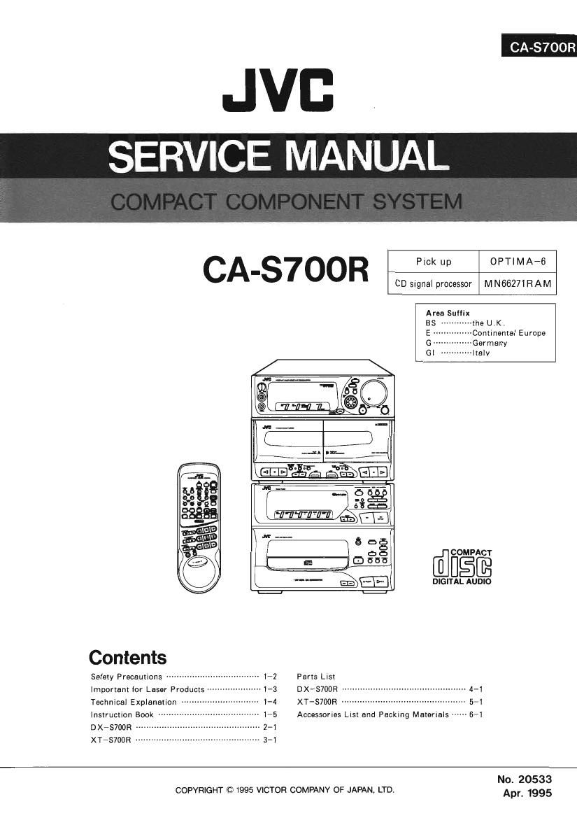
Jvc CAS 700 R Service Manual

This is the 180 pages manual for Jvc CAS 700 R Service Manual.
Read or download the pdf for free. If you want to contribute, please mail your pdfs to info@audioservicemanuals.com.

Page: 1 / 180
left right
Jvc CAS 700 R Service Manual

Extracted text from Jvc CAS 700 R Service Manual (Ocr-read)


Page 1

JVE. .
SERVICE MANUAL

CA-S7OOR

CD signal processor MN66271RAM

Area Suffix

@figé

DIGITAL AUDIO


Contents

Safety Precautions -------------------- 172 Parts List

Important for Laser Products 3 DXVS700R ------------------------------------------------ 4-1
Technical Explanation 1-4 XT-S700R ------------------------------------------------ 5-1
Instruction Book -- 1-5 Accessories List and Packing Materials 6-1
DX-S700R 2-1

XT-S700R .. 3-1

No. 20533

COPYRIGHT © 1995 VICTOR COMPANY OF JAPAN. LTD. Apr 1995

Page 2

CA-S7OOR

-$afety Precautions

1. The design of this product contains special hardware and many circuits and components
specially for safety purposes. For continued protection, no changes should be made to the
original design unless authorized in writing by the manufacturer. Replacement parts must
be identical to those used in the original circuits. Services should be performed by
qualified personnel only.

2. Alterations of the design or circuitry of the product should not be made. Any design

alterations of the product should not be made. Any design alterations or additions will
void the manufacturer's warranty and will further relieve the manufacture of responsibility
for personal injury or property damage resulting therefrom.

3. Many electrical and mechanical parts in the products have special safety-related

characteristics. These characteristics are often not evident from visual inspection nor can
the protection afforded by them necessarily be obtained by using replacement components
rated for higher voltage, wattage, etc. Replacement parts which have these special safety
characteristics are identified in the Parts List of Service Manual. Electrical components
having such features are identified by shading on the schematics and by (A) on the Parts
List in the Service Manual. The use of a substitute repalcement which does not have the
same safety characteristics as the recommended replacement parts shown in the Parts List of
Service Manual may create shock, fire, or other hazards.

4. The leads in the products are routed and dressed with ties, clamps, tubings, barriers and
the like to be separated from live parts, high temperature parts, moving parts and/or sharp
edges for the prevention of electric shock and fire hazard. when service is required, the
original lead routing and dress should be observed, and it should be confirmed that they
have been returned to normal, after re-assembling.

5. Leakage curmet check (Electrical shock hazard testing)
After re-assembling the product, always perform an isolation check on the exposed metal
parts of the product (antenna terminals, knobs, metal cabinet, screw heads, headphone jack,
contorl shafts, etc.) to be sure the product is safe to operate without danger of electrical
shock.
Do not use a line isolation transformer during this check.

0 Plug the AC line cord directly into the AC outlet. Using a "Leakage Current Tester",
measure the leakage current from each exposed metal parts of the cabinet, particularly
any exposed metal part having a return path to the chassis, to a known good earth
ground. Any leakage current must not exceed 0.5mA AC (r.m.s.).

0 Alternate check method
Plug the AC line cord directly into the AC outlet. Use an AC voltmeter having, 1,000
ohms per volt or more sensitivity in the following manner. Connect a 1,500!) 10 W
resistor paralleled by a 0.15 pF AC-type capacitor between an exposed metal part and a
known good earth ground.

AC VOLTMETER

Measure the AC volta e across the resistor -
with the AC voltmeter. g E giani'siioIQFO
Move the resistor connection to each exposed 3 °_ 0' "1°? WWW
metal part, particularly any exposed metal part
having a return path to the chassis, and 0.15}: AcTYpa
meausre the AC voltage across the resistor. -||-
Now, reverse the plug in the AC outlet and V 3: 5
repeat each measurement. Any voltage """ >§Qfih°e§§osed
measured must not exceed 0.75VAC (r.m.s.). 15009 W metal part.
This corresponds to 0.5 mA AC (r.m.s.). Good earth ground

-Warnlng

.This equipment has been designed and manufactured to meet international safety standards.

. It is the legal responsibility of the repairer to ensure that these safety standards are
maintained.

. Repairs must be made in accordance with the relevant safety standards.
. It is essential that safety critical components are replaced by approved parts.
. If mains voltage selector is provided, check setting for local voltage.

1-2

Page 101

XT~S700R

XT-S700R

- Contents -

Discription of Major LSls ............................................................ 3-2
Internal Connections of FL Display ................................................. 3-13
Disassembly Procedures ............................................................ 3-15
Adjustment Procedures ............................................................ 3-18
Flow of Functional Operation Until TOC is Read .................................... 3-19
Maintenance of Laser Pickup ....................................................... 3-20
Replacement of Laser Pickup ....................................................... 3-20
Self-diagnosis for Pickup ........................................................... 3-21
Block Diagrams .................................................................... 3-23
Printed Circuit Boards .............................................................. 3-25
Schematic Diagrams ................................................................ 3-28

3-1

Page 169

XT-S7OOR

l PARTS LIST Symbol No. [MI 3 Ml M
A Item Part Number Part Name Q'ty Description Area
1 EFP-XTSGOOREG) FRONT PANEL ASS'Y 1
1-1 E102972-2225F FRONT PANEL 1
1-2 E208408-001 WINDOW SCREEN I TUNER
1-3 E208415-001SM WINDOW SCREEN 1 CD
1-4 E406971-221 JVC MARK Z
2 E208413-001SM PUSH BUTTON 1 CD
3 E208410-0025MKP PUSH BUTTON 1 TUNER
4 95896-001 SPACER 2 FRONT FOOT
5 SDSFZEO8Z SCREW 12
6 VWF1226-16TI'B FFC CABLE 1 FC731
7 E102974-001SM CHASSIS BASE 1
8 E75896-006 FELT SPACER 2 REAR FOOT
9 SBSGSDOGM TAPPING SCREW 3
10 E208433-001 PUSH BUTTON 1 RDS
11 EWR115M-OSBB FFC CABLE 1 OPTICAL PICK-U P~ENN-431
12 806837-005 CLAMPER ASSY 1
12-1 E306836<22355 YOKE PLATE 1
12-2 94897-002 MAGNET 1
12-3 E26756-331SF CLAM PER BASE 1
12-4 E306835-221SS CD CLAMPER 1
13 EW5265-3412 SOCKET WIRE ASSY 1 5 PIN
14 EWSZGS-BMO SOCKET WIRE ASSY 1 6 PIN
15 SBSFSOOBZ TAPPING SCREW 3
16 SBST30062 TAPPING SCREW 4
17 E1 OZSSB-OOZSF CD TRAY 1
1B E406507-001 CAUTION LABEL 1
19 E406293-001 SPECIAL SCREW 1
20 -------------»- CD MECHA 1 SEE PAGE 5-4
21 ENZ8104-005 NOISE FILTER 1
22 E208419-0065MKP REAR PANEL 1
23 EWP902-046 FLAT WIRE ASSY 1 5C001
24 E408091v001 GND TERMINAL 1
25 E73273-003 SPECIAL SCREW 5
26 E208417-001SM CD FI'I'I'ING 1
27 E207787-011 METAL COVER 1
28 SDSGSOOGM TAPPING SCREW 2
29 GBSG3008CC TAPPING SCREW 4
30 VWF1223-301TB FFC CABLE 1 FC601
31 E75896-001 SPACER 1
32 SBSG3008CC TAPPING SCREW 2 TUNER PCB.
- E70891-001 CLASS 1 LABEL 1
- E61029-005 NUMBER LABEL 1
The Marks for Designated Areas
G ..... Germany GI m. Itary BS ..... the UK. EN Scandinavia
EF .... Continental Europe

No mark Indicates all area.

5-3