Jvc CAMXS 3 BK Service Manual Part 2

This is the 35 pages manual for Jvc CAMXS 3 BK Service Manual Part 2.
Read or download the pdf for free. If you want to contribute, please mail your pdfs to info@audioservicemanuals.com.

Page: 1 / 35
left right
Jvc CAMXS 3 BK Service Manual Part 2

Extracted text from Jvc CAMXS 3 BK Service Manual Part 2 (Ocr-read)


Page 1

OJNI ' S'IVHNVNEOIAHEISHEIHJ 'MMM Kq PeleTbl-G

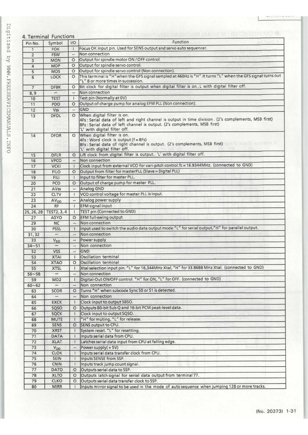
4. Terminal Functions

Pin No. Symbol IlO Function
1 FOK I Focus OK input pin. Used for SENS output and servo auto sequencer.
2 st - Non connection
3 MON 0 Output for spindle motor ON /OFF control.
4 MDP 0 Output for spindle servo control.
5 M05 0 Output for spindle servo control (Non connection).
6 LOCK O Thisterminal is 'H'when the GFS signalsampled at460Hz is"H".Itturns 'L" when the GFS signalturns out
'L' 8 or more times in succession.
7 DFBK 0 Bit clock for digital filter is output when digital filter is on , L with digital filter off.
8, 9 - - Non connection
10 TEST I Test pin (Normally at 0V)
11 PDO 0 Output of charge pump for analog EFM PLL (Non connection).
12 Vss - GND
13 DFDL O When digital filter is on.
4Fs : Serial data of left and right channel is output in time division. (2s complements, MSB first)
8Fs : Serial data of left channel is output. (2's complements, MSB first)
'L with digital filter off.
14 DFDR 0 When digital filter is on.
4Fs : Word clock is output (f = 8Fs)
8Fs : Serial data of right channel is output. (2's complements, MSB first)
'L with digital filter off.
15 DFLR 0 UR clock from digital filter is output. L' with digital filter off.
16 VPCO - Non connection
17 VCKI l [Clock input from external VCO for vari-pitch control.fc = 16.9344MHz. (connected to GND)
18 FILO O lOutput from filter for masterPLL (Slave = Digital PLL)
19 FILI I Input to filter for master PLL.
20 PCO 0 Output of charge pump for master PLL.
21 AVss - Analog GND
22 CLTV I VCO control voltage for master PLL is input.
23 AVDD - Analog power supply
24 RF | EFM signal input
25, 26. 28 TESTZ, 3,4 I TEST pin (Connected to GND)
27 ASYO O EFM full-swing output
29 NC - Non connection
30 PSSL I Input used to switch the audio data output mode.L" for serial output, H" for parallel output.
31, 32 - - Non connection
33 V03 - Power supply
34~51 - - Non connection
52 V55 - GND
53 XTAI I Oscillation terminal
54 XTAO O IOscillation terminal
55 XTSL | Xtal selection input pin. 'L for 16,344MHz Xtal, 'H' for 33.8688 MHz Xtal. (connected to GND)
56~58 - - Non connection
59 M02 1 Digital-Out ON/OFF control. 'H" for ON. 'L" for OFF. (connected to GND)
60~62 - - Non connection
63 SCOR 0 Turns 'H' when subcode Sync $0 or $1 is detected.
64 - - Non connection
65 EXCK I Clock input to output $350.
66 SQSO O |Outputs 80-bit Sub Q and 16-bit PCM peak-level data.
67 SQCK l lClock input to output $050.
68 MUTE I 'H' for muting, 'L" for release.
69 SENS O SENS output to CPU.
70 XRST I System reset. 'L" for resetting.
71 DATA I Inputs serial data from CPU.
72 XLAT l Latches serial data input from CPU at falling edge.
73 V29 - Power supply( + 5V)
74 CLOK I Inputs serial data transfer clock from CPU.
75 SEIN I Inputs SENSE from SSP.
76 CNIN i Inputstrackjumpcount signal.
77 DATO O Outputs serial data to SSP.
78 XLTO O Outputs latch signal for serial data output from terminal 77.
79 CLKO O Outputs serial data transfer clock to SSP.
80 MIRR I Inputs mirroggnal to be used in the mode of auto sequence when jumping 128 or more tracks.

(No. 20373) 1-31