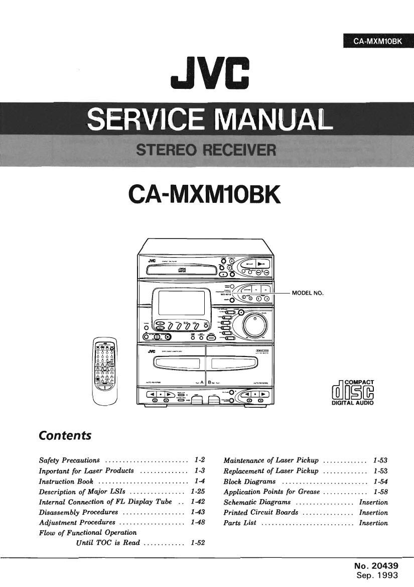
Jvc CAMXM 10 BK Service Manual

This is the 108 pages manual for Jvc CAMXM 10 BK Service Manual.
Read or download the pdf for free. If you want to contribute, please mail your pdfs to info@audioservicemanuals.com.

Page: 1 / 108
left right
Jvc CAMXM 10 BK Service Manual

Extracted text from Jvc CAMXM 10 BK Service Manual (Ocr-read)


Page 1

CA-MXM1OBK

JVI:

SERVICE MANUAL

CA-MXM1OBK

MODEL NO.
DIGITAL AUDIO

Contents

Safety Precautions ........................ 1-2 Maintenance of Laser Pickup ............. 1-53
Inportant for Laser Products .............. 1-3 Replacement of Laser Pickup ............. 1-53
Instruction Book .......................... 1-4 Block Diagrams ......................... 1-54
Description of Mqior LSIs ................ 1-25 Application Points for Grease ............. 1-58
Internal Connection 0f FL Display Tube .. 1-42 Schematic Diagram ................. Insertion
Disassembly Procedures .................. 1-43 Printed Circuit Boards ............... Insertion
Adjustment Procedures ................... 1-48 Parts List ........................... Insertion
Flow of Functional Operation

Until T00 is Read ............ 1-52
No. 20439

Sep. 1993

Page 2

CA-MXM l OBK

-$afety Precautions

1. The design of this product contains special hardware and many circuits and components

specially for safety purposes. For continued protection, no changes should be made to the
original design unless authorized in writing by the manufacturer. Replacement parts must
be identical to those used in the original circuits. Services should be performed by
qualified personnel only.

.Alterations of the design or circuitry of the product should not be made. Any design

alterations of the product should not be made. Any design alterations or additions will
void the manufacturer's warranty and will further relieve the manufacture of responsibility
for personal injury or property damage resulting therefrom.

.Many electrical and mechanical parts in the products have special safety-related

characteristics. These characteristics are often not evident from visual inspection nor can
the protection afforded by them necessarily be obtained by using replacement components
rated for higher voltage, wattage, etc. Replacement parts which have these special safety
characteristics are identified in the Parts List of Service Manual. Electrical components
having such features are identified by shading on the schematics and by (A) on the Parts
List in the Service Manual. The use of a substitute repalcement which does not have the
same safety characteristics as the recommended replacement parts shown in the Parts List of
Service Manual may create shock, fire, or other hazards.

.The leads in the products are routed and dressed with ties, clamps, tubings, barriers and

the like to be separated from live parts, high temperature parts, moving parts and/or sharp
edges for the prevention of electric shock and fire hazard. When service is required, the
original lead routing and dress should be observed, and it should be confirmed that they
have been returned to normal, after re-assembling.

. Leakage curmet check (Electrical shock hazard testing)

After re-assembling the product, always perform an isolation check on the exposed metal
parts of the product (antenna terminals, knobs, metal cabinet, screw heads, headphone jack,
contorl shafts, etc.) to be sure the product is safe to operate without danger of electrical
shock.

Do not use a line isolation transformer during this check.

0 Plug the AC line cord directly into the AC outlet. Using a "Leakage Current Tester",
measure the leakage current from each exposed metal parts of the cabinet, particularly
any exposed metal part having a return path to the chassis, to a known good earth
ground. Any leakage current must not exceed 0.5mA AC (r.m.s.),

0 Alternate check method
Plug the AC line cord directly into the AC outlet. Use an AC voltmeter having, 1,000
ohms per volt or more sensitivity in the following manner. Connect a 1,5000. 10 W
resistor paralleled by a 0.15 FF AC-type capacitor between an exposed metal part and a
known good earth ground.

AC VOLTMETER

_a

bi»

Measure the AC voltage across the resistor a (Having1ooo

With the AC voltmeter. ohms/volts, _ _ _

Move the resistor connection to each exposed O 0_ ° "W9 sens't'VW9

metal part, particularly any exposed metal part

having a return path to the chassis. and 0.15m= AC rvps

meausre the AC voltage across the resistor. --||-- .

Now, reverse the plug in the AC outlet and P'acehs
probe on

repeat each measurement. Any voltage ' each pom,

measured must not exceed 0.75VAC (r.m.s.). 150°91°W metal part.

This corresponds to 0.5 mA AC (r.m.s.). Good earth ground

- Warning

. This equipment has been designed and manufactured to meet international safety standards.
. It is the legal responsibility of the repairer to ensure that these safety standards are

maintained.

. Repairs must be made in accordance with the relevant safety standards.
. It is essential that safety critical components are replaced by approved parts.
. If mains voltage selector is provided. check setting for local voltage.

l-2 (No. 20439)

Page 4

CA-MXM 1 OBK

Instruction Book

TABLE OF CONTENTS

Control Panel and Remote - Illustrations ......mm

Features 1
How to Put Batteries in the Remote Control ................................ 2

Connection Diagrams and Instructions .
Connecting the AM and FM Antennas
AM Antenna Connections

FM Antenna Connections .
Connecting the Speakers
Connecting Auxiliary Equipmen

Read Me First ............................
How This Manual ls Organized .

Getting Started Right
Unpacking
Location
Set Up ..

. Set the VOLTAGE SELECTOR Switch

. Connect the Antennas ..

. Connect the Speakers

. Put Batteries in the Remote .

. Connect Other Sound Sources

..3

0|wa-

Common Operations
COMPUPLAY
Turning the CA-MXMIOBK 0n
Turning the CA Controlling the Sound .

Volume Control .
Sound Modes .
AI S. BASS Effect .
Using the Tuner Entry Function
Listening with Headphones
The Display and the indicators-Two Very Useful Hints

Listening to the Radio
Setting the AM Tuner Interval Spacrng
One Touch Radio
Tuning in a Station
Presetting Stations

Area Guide Preset (Available only utJapan
Receiving in Stereo or Mono .......................

Listening to a Compact D'Bc ....... ...10
Basics of Using the CD Player 10
To Play a CD... 10

How to Find the Track or a Particular Point You Want . 10
Locating a Track with the Remote 10
Programming the Playing Order of the no 10
Random Play ...... 10
Programmed Play 11

Repeating a Selection or the Entire Disc

Page 1

14 (No. 20439)

Listening to a Tape
One Touch Play .
Regular Play

.........,..ll
.11
.11

Fast Left and Fast Right . 12
Music Scan ............................................... . 12
Useful Other Features Using the Tape Deck . 12

Listeningto an Optional VTR or Turntable ..................... 12
Recording 13

Things to Know before You Start Rocordin
Standard Recording...
To Record Any Sound Source to Tape

.13
.13
.13


CD to Tape Recording. . 14
CD Direct Recording . 14
Auto Edit Recording 4

Tape to Tape Recording (
Regular Speed Dubbing . 15
HighSpeed Dubbing... .15

How to Set the Clock and Use the Timers ................................... 16
Clock Setting... ...u. .16
Setting the REC (Recording) Timer
Setting the DAILY Timer.
Setting the SLEEP Time
Timer Priority
Turning Off the CA-MXMJOBK Automatically

Karaoke (Sing Along) .......... ..
Singing Along with Karaoke
Recording Karaoke
Digital Echo for Professronal Sounding Karaoke

.15

Recording from the Microphone
Microphone Mixing ..............
Regular Microphone Recording

How to Use the Remote Control .
Using the 10 Key Pad ...........

Care and Maintenance-General Notes
Compact Discs
Cassette Tapes
Tape Dock

Troubleshooting

Specifications . ...... .22
AM Station Table (East Japan) .. G-5
AM Station Table (West Japan). 6-6

PM Station Table (East Japan --1) ...
FM Station Table (East Japan -2)
17M Station Table (West Japan) .....

Page 16

CA-MXM1OBK

What can you
record?

Jones

-Radlo

-CDs

Microphone
Connected source

Reduce hlss-
Dolby NR

Recordlng level

Erasure protectlon

Recordlng sound
mode

Usable tape type

Standard recordlng:
Any source to tape

Source to tape:
Stop by step

Page 13

1-16 (No. 20439)

Recording

Recording onto cassette tape from any of the sound sources is easy and the CA-MXMIOBK does most of the
work. Just have a tape in deck B. have the source ready, make one or two settings, and you're ready to record.

For each source the procedure is a little different and now we 1] explain just what to do toreach one. If you forget.
just come back to the section which has the specific proceduresyou need. But first. here are a few things to make

your recordings better.

Things to Know before You Start Recording:

El Press DOLBY B NR - the indicator lights up - to reduce tape hiss. except when dubbing tapes since Dolby
NR is inactive in dubbing mode regardless of the setting of DOLBY 8 NR. The dubbed tape automatically
contains the same processing as the source tape.

D The recording level. which is the volumcat which the new tape is being made. is automatically set correctly. so
it is not affected by the VOLUME control on the CA-MXM IOBK. Thus. you can adjust the sound you are actually
listening to without changing the recording

Cl Two small tabs on the back, one for side A and one for side B, can be
removed to prevent accidental erasure or re-rccording. To record on a
cassette with the tabs removed, you must cover the holes with adhesive tape
first. However, when a Type 11 tape is used, only cover part of the hole as
shown, since the other part of the hole is used to detect the tape type.

Cl When recording. you can select the sound effects with the preset sound effect buttons to condition the music as
it is recorded. But when recording using Auto Edit or CD Direct, once recording has started. these settings cannot
be changed. When recording from tape deck A to deck B. the sound effects cannot be used. because the signal
doesnt go through the amplifier fast. This method gives you the highest quality dubbed tapes.

E] Type I and type II tapes can be used for recording. While type IV tapes can be played, type lV tapes cannot be
used for recording on the CA~MXMIOBK.

CAUTION: If recordings you make have excessive noise or static. the Unit may be too close to a TV which was
on during the recording. Either turn off the TV or increase the distance between the TV and the CA-

MXMIOBK.

Standard Recording

This is the basic method for recording any source. The CA-MXM] OBK alsohas special ways for recording CD to tape,
and tape to tape. which save you time and effort. as well as give you some special effects.

However, when you need to add aselection to a tape you have made, or are combining selections from several sources
on one tape, use the method we describe here; just substitute the source you want, such as a tape in deck A. or CD, or
radio in this procedure. You can also record from the microphone or an auxil'mry source with this procedure.

To Record Any Sound Source to Tape
Follow these steps to mord from any sound source onto a tape in deck 3.
l. Insert a blank or erasable tape into deck B.
2. Press REC PAUSE.
The REC PAUSE indicator lights up.
3 Press REVERSE MODE if you want to record on both sides of the tape.
The REVERSE MODE indicator lights up.
4. Prepare the source. for example. tuning in a radio station. loading a CD, turning on a connected VTR or turntable.
5. Presseither> torocordon side/t. or< tomordonsideB ofthe tape. ondcck B.