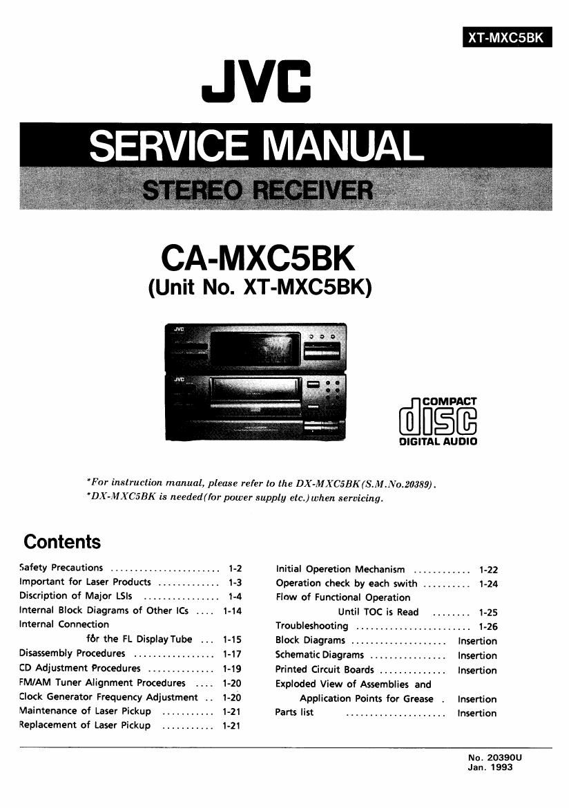
Jvc CAMXC 5 BK Service Manual

This is the 76 pages manual for Jvc CAMXC 5 BK Service Manual.
Read or download the pdf for free. If you want to contribute, please mail your pdfs to info@audioservicemanuals.com.

Page: 1 / 76
left right
Jvc CAMXC 5 BK Service Manual

Extracted text from Jvc CAMXC 5 BK Service Manual (Ocr-read)


Page 1

XT-MXCSBK

JVB
SERVICE MANUAL

CA-MXCSBK

(Unit No. XT-MXC5BK)

COMPACT

DIGITAL AUDIO

*For instruction manual, please refer to the DX-MXC5BK(S.M.:Vo.20389) .
'DX-MXCSBK is needed ( for power supply etc.) when servicing.

Contents
Safety Precautions ....................... 1-2 Initial Operetion Mechanism ............ 1-22
Important for Laser Products ............. 1-3 Operation check by each swith .......... 1-24
Discription of Major LSIs ................ 1-4 Flow of Functional Operation
Internal Block Diagrams of Other ICs 1-14 Until TOC is Read ........ 1-25
Internal Connection Troubleshooting ........................ 1-26

for the FL DisplayTube 1-15 Block Diagrams .................... Insertion
Disassembly Procedures ................. 1-17 Schematic Diagrams ................ Insertion
CD Adjustment Procedures .............. 1-19 Printed Circuit Boards .............. Insertion
FM/AM Tuner Alignment Procedures . . . . 1-20 Exploded View of Assemblies and
Clock Generator Frequency Adjustment .. 1-20 Application Points for Grease . Insertion
Maintenance of Laser Pickup Parts list ..................... Insertion
Replacement of Laser Pickup

No. 20390U

Jan. 1993

Page 2

XT-MXCSBK

- Safety Precautions

1. The design of this product contains special hardware and many circuits and components
specially for safety purposes. For continued protection, no changes should be made to the
original design unless authorised in writing by the manufacturer. Replacement parts must
be identical to those used in the original circuits.

2. Any unauthorised design alterations or additions will void the manufacturer's guarantee;
furthermore the manufacturer cannot accept responsibility for personal injury or property
damage resulting therefrom,

3. Essential safety critical components are identified by (A) on the Parts List and by shading
on the schematics ,and must never be replaced by parts other than those listed in the
manual. Please note however that many electrical and mechanical parts in the product have
special safety related characteristics. These characteristics are often not evident from visual
inspection. Parts other than specified by the manufacturer may not have the same safety
characteristics as the recommended replacement parts shown in the Parts List of the service
manual and may create shock,fire ,or other hazards.

4. The leads in the products are routed and dressed with ties, clamps, tubings, barriers and
the like to be separated from live parts, high temperature parts, moving parts and/or sharp
edges for the prevention of electric shock and fire hazard. When service is required, the
original lead routing and dress should be observed, and it should be confirmed that they
have been returned to normal, after re-assembling.

Warning

1. Service should be performed by qualified personnel only.
2. This equipment has been designed and manufactured to meet international safety standards.

3. It is the legal responsibility of the repairer to ensure that these safety standards are
maintained.

4. Repairs must be made in accordance with the relevant safety standards.
5. It is essential that safety critical components are replaced by approved parts.
6. If mains voltage selector is provided, check setting for local voltage.

1-2 (No. 20390U)

Page 7

XT-MXCSBK

PinNo, Symbol I/O Function

5° WQ 0 This terminal is connected to pCOM. It is a request signal which demands to [160M inputting
the data transfer (YM7121BtO/ACOM).

51 D' 1 This is a data input terminal connected to yCOM. when R/W is high, the data is transferred
from pCOM to YM7121B according to the SCK clock input.

53 DM + 0 These terminals output the PWM to control the speed of spindle motor, The speed of the motor

54 DM- 0 goes up when DM+ is high. and slows down when DM- is high: both terminals can not
become high simultaneously.

55 HF | When tracks are being crossed during serches,the amplitude variation of the generated H F signal is

56 TER I sampled at the zero - cross point of the tracking error signal TER and the TROF signal is output. The

60 TRHD O , . . . . . . . . .

61 TRGL 0 level variations ofthls sIgnalturn the servoon and off,greatly facilitaing track acqur51tion.KP+ or

62 TROF O KP - is output to conduct tracking, and TRHD is output during tracking to cause generation of the

63 KP _ O tracking error signal. The TRGL signal is for increasing the tracking gain aftertracking is completed.

64 KP + 0

3; gm: 8 The FEM+ and FEM- are output as high speed feed signals, and FEOF signal is output for

59 FEOF 0 cutting the feed servo during high speed feed.

65 TREK I TRBK is input to apply tracking brake from outside. TRGL becomes low with high input and
inner control signal TBKE becomes high.

66 SVOF ' when the signal inputsto SVOF ,tracking and feed srvo settoOFF. TROF and FEOF become
'H" with high input, and TRHD, KP+. KP- become low.

67 cm I These terminals are used for controlling the focus servo.

53 FCS O The FCS is fora leading signalof Focusing; the signal, generated when the

59 FRF I focus point is achieved, terminate the focusing operation; and FCC flag is dropped internally by
FRF signal generated when reflected light is detected.

71 lC I YM71218 needs initializing when power supply turn on.

IC will be low more than 400,5 since XIN is input clock with VDD standard.

73 SLVL o Amplitude limited, mutually anti-phased signals are output from EFMX and-Em.

74 EFMX 0 Slice level is controlled by these signalsand external amplifier. SLVL is output amplitude
75 m 0 alteration component of both terminals. When integral circuit is connected to external.
YM712lB easily can control slice level.

76 EFMI I This terminal is input EFM signa|.( l~2Vpp)

73 PCO 0 This terminal outputs the phase difference when the polarity of the clock and the EFM pattern
changes.

79 VPLL i This terminal is input DC. voltage matched VCO free run. frequency. (17,2872 MHz)

80 1/2 VPLL O This terminal outputs a half of VPLL input, and capacity for stabilizing is added to this terminal.

(No. 20390) 1-7