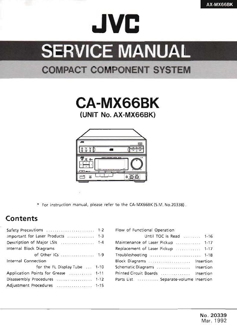
Jvc CAMX 66 BK Service Manual

This is the 48 pages manual for Jvc CAMX 66 BK Service Manual.
Read or download the pdf for free. If you want to contribute, please mail your pdfs to info@audioservicemanuals.com.

Page: 1 / 48
left right
Jvc CAMX 66 BK Service Manual

Extracted text from Jvc CAMX 66 BK Service Manual (Ocr-read)


Page 1

AX-MXGGBK

JVD

SERVICE MANUAL

COMPACT COMPONENT SYSTEM

CA-MX66BK

(UNIT No. AX-MX6SBK)

* For instruction manual, please refer to the CA-MX668K(S.l\/l. No.20338)s

Contents

Safety Precautions ....................... 1-2 Flow of Functional Operation

Important for Laser Products ............. 1-3 Until TOC is Read ........ 1-16

Description of Major LSls ............... 14 Maintenance of Laser Pickup ............ 1-17

Internal Block Diagrams Replacement of Laser Pickup ............ 1-17
of Other [(25 ................ 1-9 Troubleshooting ....................... 1-18

Internal Connection Block Diagrams .................... insertion
for the FL Display Tube _.. 1-10 Schematic Diagrams ................ lnsertion

Application Points for Grease ........... 1-11 Printed Circuit Boards .............. Insertion

Disassembly Procedures ................. HZ Parts List .......... Separatewolume Insertion

Adjustment Procedures ................. 1-15

No. 20339
Mar. 1992

Page 2

AX-MXGGBK

-Safety Precautions

1. The design of this product contains special hardware and many circuits and components
specially for safety purposes. For continued protection, no changes should be made to the
original design unless authorized in writing by the manufacturer. Replacement parts must
be identical to those used in the original circuits. Services should be performed by
qualified personnel only.

2. Alterations of the design or circuitry of the product should not be made. Any design
alterations of the product should not be made. Any design alterations or additions will
void the manufacturer's warranty and will further relieve the manufacture of responsibility
for personal injury or property damage resulting therefrom.

3. Many electrical and mechanical parts in the products have special safety-related
characteristics. These characteristics are often not evident from visual inspection nor can
the protection afforded by them necessarily be obtained by using replacement components
rated for higher voltage, wattage, etc. Replacement parts which have these special safety
characteristics are identified in the Parts List of Service Manual. Electrical components
having such features are identified by shading on the schematics and by (.L.) on the Parts
List in the Service Manual. The use of a substitute repalcement which does not have the
same safety characteristics as the recommended replacement parts shown in the Parts List of
Service Manual may create shock, fire, or other hazards.

4. The leads in the products are routed and dressed with ties, clamps, tubings, barriers and
the like to be separated from live parts, high temperature parts, moving parts and/or sharp
edges for the prevention of electric shock and fire hazard. When service is required, the
original lead routing and dress should be observed, and it should be confirmed that they
have been returned to normal, after re-assembling,

5. Leakage currnet check (Electrical shock hazard testing)
After re-assembling the product, always perform an isolation check on the exposed metal
parts of the product (antenna terminals, knobs, metal cabinet, screw heads, headphone jack,
contorl shafts, etc.) to be sure the product is safe to operate without danger of electrical
shock.
Do not use a line isolation transformer during this check.

0 Plug the AC line cord directly into the AC outlet. Using a Leakage Current Tester",
measure the leakage current from each exposed metal parts of the cabinet, particularly
any exposed metal part having a return path to the chassis, to a known good earth
ground. Any leakage current must not exceed 0.5mA AC (r.m.s.).

0 Alternate check method
Plug the AC line cord directly into the AC outlet. Use an AC voltmeter having, 1,000
ohms per volt or more sensitivity in the following manner. Connect a 3.5000 10 W
resistor paralleled by a 0.l5 #F AC-type capacitor between an exposed metal part and a
known good earth ground.

Measure the AC voltage across the resistor a gigxggmggm
With the AC voltmeter. ohms/volts, _
Move the resistor connection to each exposed O Q 0' WESQNSWWW-i
metal part, particularly any exposed metal part
having a return path to the chassis, and 015.,i=Ac TYPE
meausre the AC voltage across the resistor -||-
Now, reverse the plug in the AC outlet and Place this
repeat each measurement. Any voltage M" >2gifieeigosed
measured must not exceed 0.75 VAC (r.m.s.). 1500010W metal part.
This corresponds to 0.5 mA AC (r.m.s.). Good earth ground

-Warning

1. This equipment has been deSigned and manufactured to meet international safety standards.

2. it is the legal responsibility of the repairer to ensure that these safety standards are
maintained.

3. Repairs must be made in accordance with the relevant safety standards.
4. It is essential that safety critical components are replaced by approved parts.
5. If mains voltage selector is provided, check setting for local voltage.

1-2 (No. 20339)

Page 3

Important for Laser Products

CLASS 1 LASER PRODUCT

DANGER: Invisible laser radiation will cause when
open and interlock failed or defeated, Av0id direct
exposure to beam,

CAUTION :There are no serviceable parts inside the
Laser Unit. Do not disassemble the Laser Unit. Replace
the complete Laser Unit if it malfunctions.

4. CAUTION :The compact disc player uses invisible
laser radiation and is equipped With safety switches
which prevent emission of radiation when the drawer
is open and the safety interlocks have failed or are
defeated. It is dangerous to defeat the safety
switches.

5.

AX-MXGBBK

CAUTION : If safety switches malfunction. the

laser is able to function.

6. CAUTION : Use of controls, adjustments or
performance of procedures other than those
specified herein may result in hazardous radiation
exposure.

7. CAUTION '. The compact disc player provides a
laser diode of wavelength 760-800nm and optical
output power typical 3mW at the laser diode.

VARNING EOSynlig laserstrélning nfir denna del 5r
appnad och sparren 3r urkopplad. Betrakta
ej strélen.

VARO : Avattaessa ja suojalukitus ohitettaessa olet

alttiina nakymattcimalle Iaserséteilylle. Ala
katso séteeseen.

ADVARSEL: Usynlig laserstréling ved ébning nér
sikkerhedsafbrydere er ude ai funktion. Undgé
udsaettelse for stréling.

ADVARSEL : Usynlig laserstréling ved Spning, nér
sikkerhetsbryteren er avslott. unngé utsettelse for
stréling.

REPRODUCTION AND POSITION OF LABELS

WARNING LABEL
(Except forthe U. S. A.)

DANGER invisiblehser VARNING: Dsynling laser-

radiation when open and
interlotii failed or defeated.

siraiing nar denna del
aoppnad och sparren 5r

srrAImg ved ebmng, nér
sikkeriiedsaibrydere er ude
at lunktion. Undgaudsaet-
(else rm strAIing (a)

AVOID DiREcr EXPOSURE uriroppled Beirakra ej
TO BEAM. (e) slélen (s)
ADVARSEL: Usynllng lasei- VARO: Avanaessaja suo-

'aiukiius oiiiteuaessa oiei
aimina naiymanbmalle
iasersateilyile. Ala karso
sateeseen. (r)

I.

8-8- - fl
0..
. :I

CLASS 1
PRODUCT

LASER

CLASSIFICATION LABEL
(Except for the U. S. A. and Canada)

(No.20339) 1-3

Page 14

AX-MXEGBK

I Laser Pickup removal

1. Remove the top cover, tray assembly and the

clamp.

2. Move the Pickup unit from rest position to the
center pushing (53 point with finger.

3. Remove the screw CZ from the CD Rack assembly,
and remove the CD Rack assembly.

4. Remove the screws 6 i from the CD mechanism
base assembly.

5. Remove the CD Holder fastening the shaft from
the CD mechanism base assembly. (Release the
hook @)

6. Remove the CD Pick Unit with the shaft.

I CD Pick Unit installation

1. Connect two wires with the connectors of APC
P.C.Board.

2. While installing the "v in the CD Support, set the
shaft on the base hook i .

3. Install the CD Holder.

4. Install the CD Rack assembly in the CD Pick
Unit.
1) Fit end 7,
2) Fix screw 4 .

CD mechanism base assembly

CD Holder
CD Rack
assembly
,/
@\ Q (D
<3 ®
I /
CD (3 . .
Support CD Pick Unit
Figure 7

I Spindle motor removal

Remove the CD mechanism base assembly.

2. Remove the turntable, and remove the two screws
retaining the spindle motor.

3. Remove the screws retaining the Spindle and

Feed Motor P.C. Board and unsolder it.

H

1-14 (No.20339l

Turntable . Spindle motor retaining screws
.

Figure8

I Spindle motorinstallation

1. Tighten the 2 screws to the same torque.

2. Fasten the Spindle and Feed Motor RC. Board
with the screw and solder.

3. Install the turntable.When installing, press
straight down at the center of the turntable until
the distance from the surface ofthe mechanism
base to the top of the turntable is exactly
12.0 i 0.1mm.

{

Figure9

4. After insertion is complete, bond the motor shaft
and turntable together (at the section marked by
an arrow in the figure 10 on the left below),

CORRECT

-- lNCORRECT

K

FigureiO

5. Use LOCKTITE #460 bonding agent, and apply
as little as possible, Take care not to allow any
excess bonding agent to get onto the turntable. Be
extremely careful not to allow bonding agent to
adhere to the motor bearings (the section marked
by an allow in the figurelo on the right).