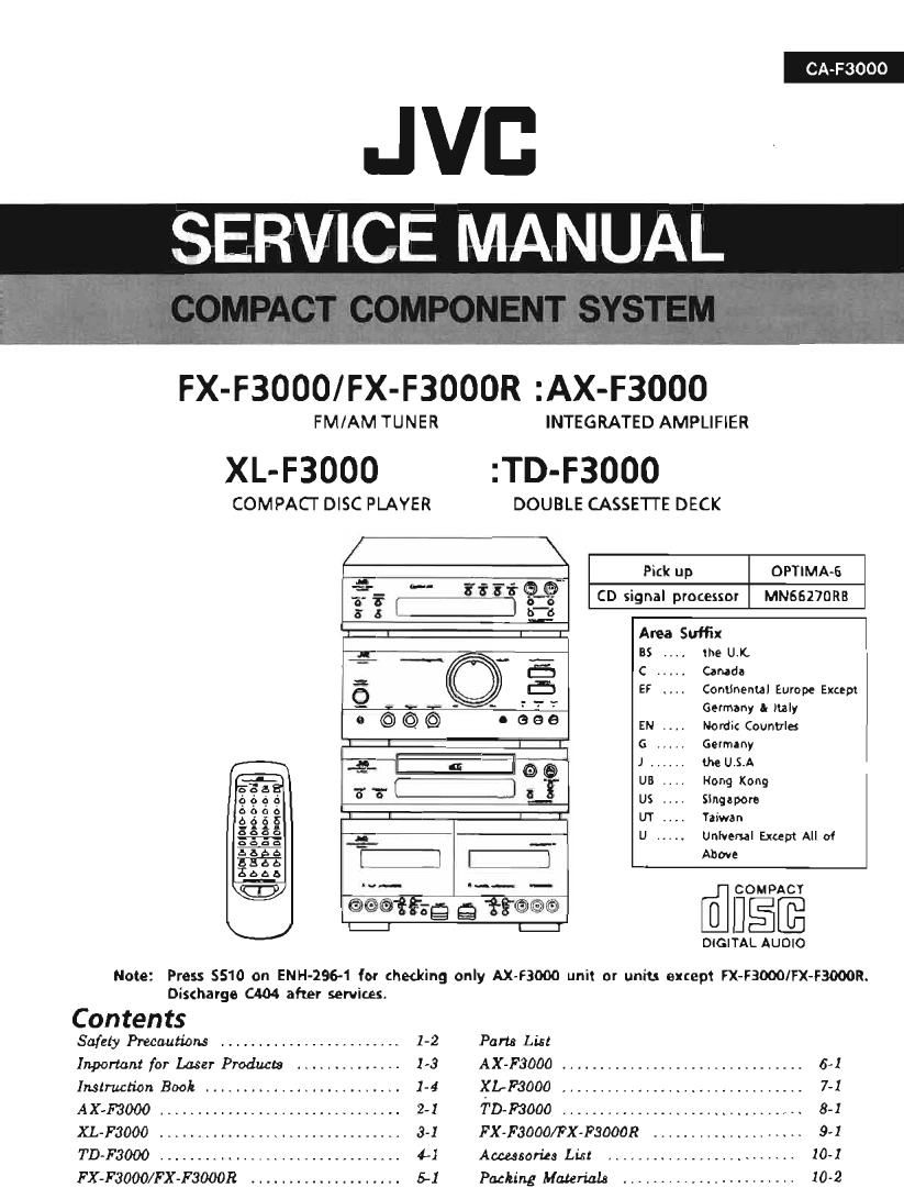
Jvc CAF 3000 Service Manual Part 1

This is the 90 pages manual for Jvc CAF 3000 Service Manual Part 1.
Read or download the pdf for free. If you want to contribute, please mail your pdfs to info@audioservicemanuals.com.

Page: 1 / 90
left right
Jvc CAF 3000 Service Manual Part 1

Extracted text from Jvc CAF 3000 Service Manual Part 1 (Ocr-read)


Page 2

AX-F3000

AX-F3000

Note: Press 5510 on ENH-296-1 for checking only AX-F3000 unit or units
except FX-F3000/FX-F3000R.
Discharge C404 after services.

Contents
Description of Major ICs ............................................................ 2-2
Disasssembly Praceduers ............................................................ 2-5
Adjustment Procedures .............................................................. 2-8
Block Diagram ..................................................................... 2-9
Printed Circuit Boards ............................................................. 2-10
Schematic Diagrams ............................................................... 2-13

2-1

Page 19

m S: : m 82 a m mm: a . m m
o 3; :1m 8% a m a: A g N m
u $5 m w 333: . a 3; b _ N m
m 8% N a 33 A m m m
9 8E _ 0 Em # a m m
m 32 m x 33 a m m m
n 28 m : man 5 m V x m
m 88 4 x 3mm 9 m m I x,
m 8% m : Eww w m V L »
m 38 V 2 33 m m m L >
m. 88 m I 3% _ m V L m
m 82 N _ Ea 4, w m g m
0 Bow a w Ema m m N L a
,ma, 2% m L 33 A o: m L
m 33 a L 3% 4 I N L
w an: N L 33 m x Q L
o S; m 9 £3 ,:_ a m
m 2; w A 38 a m 3% a m a
L 2: m _ E3 A m 3% m m .n
83 a m 9:3 3 o 38 m > £2 E a fig 3 a m
8: a m of: u x ES 8 > 38 Q a 32 a m
a; a a 959 E o 29 a m £8 a a fig 3 m
wmo a o 958 a m 38 3 m 22 a a 3% m )
my a a SS m m 28 m m 33 a m 3% a )
8S 3 o 88 fl 0 BE 3 m 38 a m 32 a >
83 a a 33 d o 88), 4 m 53 a o 3% a >
8: A o 3:: a (w 33 m m 3% a o 33 m w
83 N o S; m L 23 w m a: a > 22 : w
83 m a S; m L 2% 3 m E: a m flmw. w m:
8: w a; E: a Q 2% N > £3 a w £2 m
91%? 88 , m, 33 M m 23 o > 33 Am r 32 _ .m,_
{a 83 m m 3% M m 2: w > 3% 3 fl 3% m
:5; V 88 A m 38 m L is : > a: N ca 3% >
O 8: L,» m 3: N . SE a m , g 33 >
o /I\ 83 A u .3» m _ 2.: : m 3: m
owwm N c 3; u 7 38 w m 23m m
H O 8% # o 3: m 3% o m 33 m
88 m u 33 m A 28 a m 2a m
88 o 33 m m 2% 3 m as m
28 N a ES 3 m 82 m > 38 m

P2-11-C

Page 79

TD-F3000

Removing the door lock plate assembly

1. Remove the mechanism assembly.

2. Remove the 2 screws (9 fixing the
assembly.

3. Open the cassette doors to remove the
assembly.

(5)

Removing the cassette lids

1. Push the eject button to open the cassette
doors.

2. Slide the lids up to remove them.

(6)

Door lock plate

® assembly
0 /
o o '1 o 0
DE!
/
®

Front panel

Cassette lid _>

Removing the dumpers

1. Remove the mechanism assembly.

2, Press the hook and release it to remove the
dumper. (See an arrow)

(7)

Removing the Cassette holder
1. Remove the mechanism assembly.
2. Open the cassette door.
3. Remove the spring.
4. Remove the cassette holder.

(8)

4-6

Front panel assembly

Cassette
holder
3
HM O 0
% Dumper
® SDSFZSOSZ

Page 83

TD-F3000

Adjustment Procedures (Cassette Deck)
1. Measuring instruments

Audio frequency signal generator ( Odhs output at the 600 ohm output terminal from 50Hz to ZOKHz)

Electronic voltmeter
Frequency counter
Wow & Flutter meter

Distortion Meter with band pass filter

Attenuator (600 ohm impedance)

A resistor with 6000

Standard Tape 0st=0.775V
Tape No. Frequency Level (Wow & Fkutter) Purpose
VTI»703L 10kHz -10st Head alimuth , Frequency Response
VTr-712 3000Hz ()st 0.025%WRMS Tape Speed , WowfluFlutter
V'l'rv724 lkHz -4st Standard Level
TMT-6447 - - Blunk Skip
TMT-6247 , TMT-6237 - - Music Scan

TMT-7046 - - Recording standard Normal : UR
AC-712 - - Recording standard METAL: MA
AC-513 - - Recording standard GORSA

TW-2111,TW-2121 - -

Forward/reverse play torque measuring

TW-2231 - - Feed forward/rewind torque measuring
C-120 Tape - - Comfirming the tape running
2. Adjustment and repairing the mechanism
Item Adjustment method Standard Remarks
value
DeckA 1. Refer to figure 1.
1. Connect an electronic voltmeter to the DOLBY , , , _
H d TP(figure 3) to playback VTT-703L M _ 2. When the specified characteristic cannot be
. a . .
azirenauth 2. Adjustscrew®so that the indication of the Ximum obtained 3 01 head wear, excessive
voltmeter becomes maximum when PLAY (b) is magnetization, 9" replace the head
pressed. assembly and adjust the head aZImuth,

3. Adjust screw®so that the indication of the Alo' perform the Elem adjustment,
voltmeter becomes maximum when PLAY (4) is 3. When there is the difference of more than
pressed. 3~4 dB between left and right output

Deck 8 levels, replace the head assemblyto avoid

4. Adjust screw ©so that the indication of the complaints.
voltmeter becomes maximum when PLAY (D)
is pressed.

5. Adjust screw @513 that the indication of the
voltmeter becomes maximum when PLAY (4)
is pressed.

6. After making the adjustment,apply screw lock to
prevent screws ®, @, ©and ®coming loose.

Playback 1. Measure the torque in the playback mode by 26-. 62 When the standard torque cannot be obtained,
torque the torqu meter. g_(m replace the FR arm assembly ormotor,
F351 forward 1. Measure the torque in the fast forward mode 80~ 170 When 19 standard torque cannot be
torque by the mm may, 9., obtainedreplace the FR arm assembly or motor.
Rewind 1. Measure the torque in the rewind mode by 80-- 170 When the 513'an torque cannot be
torque the torqu meter. 9.0- obtained, replace the FR arm assembly or motor.
WOW 1. Connect the wow& flutter meter to the _ As a complaint may occur if the wow 8: flutter
& DOLBY TP(figure 3) and play back Vl'|'-712 g fluctuates by 0.1% even though it is allowed
flutter 2_ Its reading should be within 01% (WTD), in the standard, repairing is required,
® (3 © ®
Deck A Figure1 Deck B

mo