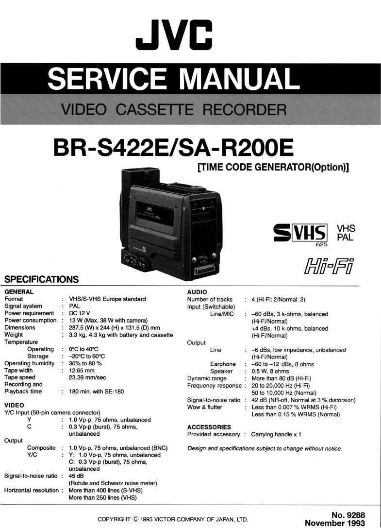
Jvc BR SAR200 E Service Manual Part 1

This is the 50 pages manual for Jvc BR SAR200 E Service Manual Part 1.
Read or download the pdf for free. If you want to contribute, please mail your pdfs to info@audioservicemanuals.com.

Page: 1 / 50
left right
Jvc BR SAR200 E Service Manual Part 1

Extracted text from Jvc BR SAR200 E Service Manual Part 1 (Ocr-read)


Page 1

JVB
SERVICE MANUAL

BR-S422E/SA-R200E

[TIME CODE GENERATOR(Option)]

SVHS $213

625

HiDFi

SPECIFICATIONS

GENERAL AUDIO

Format VHS/S-VHS Europe standard Number of tracks : 4 (Hi»Fi: 2/Normal: 2)

Signal system PAL Input (Switchable)

Power requirement DC 12 V Line/MIC : -60 L185, 3 k-ohms, balanced

Power consumption 13 W (Max. 38 W with camera) (Hi-Fi/Normal)

Dimensions 2875 (W) x 244 (H) x 131.5 (D) mm +4 st, 10 k-ohms, balanced

Weight 3.3 kg, 4.3 kg with battery and cassette (Hi-Fi/Normai)

Temperature Output
Operating 0°C to 40°C Line : -6 st. low impedance, unbalanced
Storage -20"C to 60°C (Hi-Fi/Normal)

Operating humidity 30% to 80 % Earphone : -60 to -12 st. 8 ohms

Tape width 12.65 mm Speaker : 0.5 W, 8 ohms

Tape speed 23.39 mrn/sec Dynamic range : More than 80 dB (Hi-Fi)

Recording and Frequency response : 20 to 20,000 Hz (Hi-Fi)

Playback time 180 min. with SE-180 so to 10,000 Hz (Normal)

so Signal-to-noise ratio : 42 dB (NR-oft, Normal at 3 % distorsion)
VID

Y/C Input (50~pin camera connector)
Y :

0
Output
Composite
Y/C
Signal-to-noise ratio :

Horizontal resolution :

1.0 Vp-p, 75 ohms. unbalanced
0.3 Vp-p (burst), 75 ohms,
unbalanced

1.0 Vp-p, 75 ohms, unbalanced (BNC)
Y: 1.0 Vp-p, 75 ohms. unbalanced
C: 0.3 Vp-p (burst), 75 ohms.
unbalanced

45 dB

(Hohde and Schwarz noise meter)
More than 400 lines (S-VHS)

More than 250 lines (VHS)

Wow & flutter : Less than 0.007 % WRMS (Hi-Fi)
Less than 0.15 % WRMS (Normal)

ACCESSORIES
Provided accessory : Carrying handle x 1

Design and specifications subject to change without notice.

COPYRIGHT © 1993 VICTOR COMPANY OF JAPAN, LTD.

No. 9288
November 1993

Page 2

TABLE OF CONTENTS

Section Title Page

Important Safety Precautions
INSTRUCTIONS
1. GENERAL DESCRIPTION AND DISASSEMBLV

1.1 REMOVAL OF ENCLOSURE PARTS.
.1.1 Cassette paneI assV .......

I
1 1 2 Left 51de cover
1 1 3 Battery holoer assy
1 1.4 Top cover assv . .
1 1.5 RIght sIde cover assy . H
1 1.6 Front cover assv ......
11.7 Rear panel . 1-2
I 1.8 Connector box assy 1-2
1.1.9 Bottom cover assy
1.2 REMOVAL OF MAIN BOARDS
12.1 Group A ........................
1.2.2 GroupB .......
1.2.3 GroupC .. .....
12.4 Group D .
1.2.5 GroupE .....
1.3 REMOVAL OF CASSETTE HOUSING .. ...
1,4 INTERNAL SWITCHES
141 E] VIDEO board ,
1.42 [E] AUTO E0 board ,.,
1.4 3 @ AUDIO board ........
1.44 @I DISPLAY board... ........................
1.4 5 131E TIME CODE board ISA-RZOOE. OpIIohal) .
1.5 HOUR METER DISPLAY ......

1.5.1 How to reset the hour meter .....
1 6 BATTERY CONNECTOR ............
17 EMERGENCY EJECT ........
TABLE OF SCREWS USED IN THIS SET

18
1'9

2, MECHANISM ADJUSTMENT

21 PREPARATION. .2-1
2.1.1 PrecautIonsu . . .2-1
2.1.2 Jigs and speCIaI tools for mechanism adjustment . 2-1
2.1.3 SpecIfIcatIDns of aIIgnmehttapes ..... . 2-1

2.2 PERIODIC REPLACEMENT OF MAIN PARTS .. . 2-2
2.2.1 Location of mam parts ................ .. 2-3

2.2.2 Maintenance step of man pans

2.2.3 AdIustmems requIred aIter replacement of drum

assembly ........ . .......

2.2.4 AdIustmem required after repIacement ofA/C head .. 2-5

2 2 5 CleahIng . . .

2. 2. 6 OIIIng and greasing ........ .
2,3 REPLACEMENT OF MAIN PARTS..

2.4 REASSEMBLING OF MECHANISM ..

..2-14

2.5 TAPE TENSION ADJUSTMENT.
2 6 INTERCHANGEABILITY ADJUSTMENT . .. 2-15
2.7 ADJUSTMENT OF TAPE TRANSPORT SYSTEM ........ . 2-20
2 8 TABLE OF SCREWS AND SLIT WASHERS USED

IN THIS SET ................ . ......... .....2-21

Section Title Page

3. ELECTRICAL ADJUSTMENT

31 PRECAUTIONS .. ....... 3.1
31 1 RequIred tools and test Instruments .3-1
31.2 Specrflcauon of alIgnmerIt tapes . 3-2

31 3 SIgnaI requIred for vxdeo system adlustment 3-3

3.1.4 InitiaI signaI of swmches
3.2 REGULATOR CIRCUIT ..........
3.3 SERVO CIRCUIT
3.4 AUDIO CIRCUIT
3.5 VIDEO CIRCUIT
LOCATION OF TR & VR

4. DIAGRAMS AND CIRCUIT BOARDS
4.1 FOREWOED ...................................................... .41
4.1.1 Expressmn ofw1ring . ........
4.1.2 SighaI IIow on the dragram .
4.1 3 Measurement of voItage and waveform
4.14 UhIt oIvaIue .. .
41 5 CIrcuIt board IocatIorIs ,
41 6 Shapes of tranSIstor & dIodes ..
4 2 MOTHER CIRCUIT BOARD .. .
4,3 OVERALL WIRING DIAHGRAM ..................
4.4 VIDEO BLOCK DIAGRAM
4,5 AUDIO BLOCK DIAGRAM
4.6 SYSCON/SERVO BLOCK DIAGRAM 11/2).
4.7 VIDEO SCHEMATIC DIAGRAM (1/3) .....
48 VIDEO CIRCUIT BOARD .. . ..
4.9 C. RF SCHEMATIC DIAGRAM
4.10 C RFCIRCUIT BOARD
4.11 AUTO EO SCHEMATIC DIAGRAM
4.12 AUTO EO CIRCUIT BOARD .......
4.13 PRE/REC SCHEMATIC DIAGRAM
4.14 PRE/REC CIRCUIT BOARD ..
4.15 PRE/REC JUNC SCHEMATIC DIAGRAM AND
CIRCUIT BOARD .................
416 POWER CTL SCHEMATIC DIAGRAM AND CIRCUIT

BOARD .................................... .. 423
417 AUDIO SCHEMATIC DIAGRAM I1/2I .4-24
4.18 AUDIO CIRCUIT BOARD .............. .. 4-26
4.19 SYSCON/SERVO SCHEMATIC DIAGRAM .. 4-28

4.20 SYSCON/SERVO CIRCUIT BOARD ........ . 4 28
4.21 50 PIN SCHEMATIC DIAGRAM AND CIRCUIT BOARD. 4 30
4 22 OPERATION SCHEMATIC DIAGRAM AND CIRCUIT

BOARD ..... .....................
4.23 REGULATOR SCHEMATIC DIAGRAM
4.24 REGULATOR CIRCUIT BOARD
4.25 MDA SCHEMATIC DIAGRAM .....
4.26 MODE SENSOR MDA MECHA IF MECHAJUNC

END SENSOR, START SENSOR. MDA JUNC, POWER SW.

A/C HEAD, REEL SENSOR CIRCUIT BOARDS ............. 435
4 27 CONNECTOR CIRCUIT BOARD ................ 4-35
4.28 MECHA IF, MECHA JUNC SCHEMATIC DIAGRAM 4-36
429 LCD SCHEMATIC DIAGRAM . ................ 4-37
4 30 TIME CODE SCHEMATIC DIAGRAM [SA RZOOE OPTION) 4 38
4 31 TIME CODE CIRCUIT BOARD ISA-R200E OPTION) 4- 39
4.32 IC BLOCK DIAGRAM . ... . ....... 4-40

4.31
4-32
4.33
4-34

Page 24

1.2 REMOVAL OF MAIN BOARDS

Note: Whenever intending to remove or reinstall any board, make sure to disconnect the power cord. Ali boards that were
removed or disconnected once must be reinstalled or reconnected as they were,

@lAUDIO
@EDISPLAY
fl-PRE/REC JUNC

Group Board Name Removing Procedure
A EEVIDEO 51) Remove the right side cover assv (refer to ii 5\
@lC. RF 2) Proceed to do things described in "i.2 1 Group A
@IEA. E0
@ESYSCON/SERVO
@EREGULATOR

B EEPRE/ REC

(1', Remove the ieft Side cover essy (refer to H 2)

(2: Proceed to do things described in i,22 Group B

C 3 EjJMOTHER

(1"; Remove the bottom cover assy (refer to H 9).

(2i Remove the right side cover assy (refer to H 5)

23] Remove the ViDEO, the SYSCON/SERVO,
REGULATOR and the PRE/REC JUNC board.

:4] Proceed to do things described in i2.3 Group C"

the

D EEPOWER CTL
EECONNECTOR

Q1) Remove the connector box assy (refer to L18),

(2') Proceed to do things described in 12.4 Group D

E EEOPERATION

iii} Remove the top cover assy (refer to (14)

[2) Proceed to do things described in "i 2.5 Group E

1'3

Page 39

No. Item

Adjustment and Check

3 Head cleaner

, , Pull up the cleaner (sponge) a little while taking it out.

l i y
l FF brake SEARCH brake

Fig. 2-3-8 Removal of brakes

Cleaner 1(2) Replace it With a new cleaner in the reverse order of
PM up the W / i removmg
sponge up- . i
wards \%
\ a
Fig. 2-3-5 Removal of Head cleaner
4 Tension band assy ll} Remove a screw C2) and disengage the tension band from the
A: portion of the tension pole assy.
A portion TeHSlon 906 555V (2) Operate the FF brake while taking out the tenSion bandi
\ l
\ , . .
~ FF brake [3) Engage a new ten5ion band in the original posmon.
1[4-) After replacement, check and adjust the tension pole
position and back tension (see 2.5.1, page 2-14)
SP reel disk 7 Tension band essy
Fig. 2-3-6 Removal of Tension band
l
5 Pinch roller 3[1) Remove a screw 3 and detach the pinch roller and its
peripheral parts.
[2) install a new pinch roller and fix the collar and the pinch
roller cap With the screw.
Fig. 2-3-7 Removal of Pinch roller
6 FF, REW, SEARCH brake assembly (1) - REW, SEARCH brake -
Lift the FiEW and SEARCH brake assemblies upwards
with nippers or the like while press the locking pawl of
REW brake themi
l
(2) - FF brake -

Remove a slit washer @ and lift the FF brake upwards
while taking it out.

2-8

Page 41

No.

Adjustment and Check

9 Drum assembly

F E head assy
\

Release arm assy Cleaner arm assy

Fig. 2-3-12 Removal of the drum assy

Remove the compoments in the following order.

The cassette panel (see 1 1.1, page 1-1).

The left side cover assembly (see 1.1.2, page 1-1).
The connector box (see 1.1.8, page 1-2).

The PRE/REC board assembly (see 1.2.2, page 141).

Remove a screw 3, and take out the cleaner arm assembly.

Remove three screws i and draw out the drum assembly
diagonally to the front Side trying to avoid the FE head
assembly and release arm assembly.

With careful attention to the drum assembly to prevent it
from getting damaged, install a new drum motor assembly
in the reverse order of disassembly, Tighten screws evenly.

Perform adiustments required after replacement of the
drum assembly (see 2.2.3)

10 Loading motor
Loading belt

Fig. 2-3-13 Removal of the loading motor and belt

Remove the compoments in the following order.

The right side cover assy (see 1.1.5, page 1-1).

The video board (see 1 2.1, page 1-4),

Disconnect the CN6 from the M ii: board.

Remove two screws 6?) and take out the motor bracket.

Remove two screws @ and disconnect wires from the
loading motor.

Disengage the loading belt and take out the loading motor.
Install a new loading belt and a new loading motor in the

reverse order of the removal. When Wiring, pay attention to
the polarity of Wires.

Poles of motor Color of wire

4,
(Red marking) Red

- Gray

Fig. 2-3-14 Polarity of the loading motor

11 Capstan motor

Reel belt

Capstari motor

Fig. 2-3-15 Removal of the capstan motor

Note: Be careful not to damage the capstan shaft.

Remove the compoments in the followmg order

The right side cover assy (see 1.1.5, page 1-1).

The video board, the 8/8 board and the REGULATOR
board (see 1.2.1., page 1-4).

The MECHA JUNC board (see 1.2.3 No.(2), page1-A),

Disengage the reel belt from the capstan motor and discon»
nect the CN2 from the M 1F board,

Remove three screws 3 and remove the capstan motor.

When installing the capstan motor. place it in the A/C
head Slde.

2-10