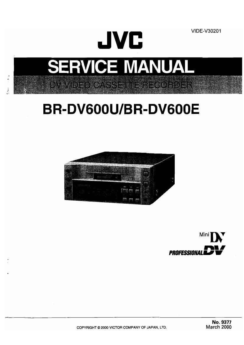
Jvc BR DV 600 U Service Manual Part 1

This is the 116 pages manual for Jvc BR DV 600 U Service Manual Part 1.
Read or download the pdf for free. If you want to contribute, please mail your pdfs to info@audioservicemanuals.com.

Page: 1 / 116
left right
Jvc BR DV 600 U Service Manual Part 1

Extracted text from Jvc BR DV 600 U Service Manual Part 1 (Ocr-read)


Page 49

1.10 BACKUP OF TIME DATA

The BR-DVBOO uses a polyacene battery (C40) to back up the
LCD microcomputer on the Front board assembly. This is the
same battery as that used in the SR~907O and a secondary bat-
tery with a capacity of more than 2 F (Farads). It is capable of
backup for about 60 hours with only 6 hours of power supply

1.11 SET UP SW (U-MODEL ONLY)

Menu SW No. 125 is the SET UP ON/OFF switch. its setting
affects the recording and playback of analog video signals.

0 Recording signals ..This switch varies the sampling level

for AID conversion of the input signal.

I Playback signals This switch adds the setup level to the

(OPERATE ON), the backed up data includes the following: playback signal
(1) TC generator data (In the free run mode, the count contin<
ues even during backup.) SET UP _ _
(2) Date and time data for subcodes, ("05:25) WM"? 3'99" Playback 5'9"
l3) CTL counter data,
Executes A/D conversion Adds the setup level.
. . from the setup level.
1.10.1 Backup Circuit
235 ----------- 100%
The backup current to the polyacene battery is switched by IC10 ON
on the Front board. When UNSW + 5 V drops below 4.6 V, this 15 ________
lC switches the microcomputer power to the LCD to the Sstuv'm'
polyacene battery, At this time, IC10 sets the CS output to the {3963 m'
Low level, the LCD microcomputer switches the clock oscilla-
tor to the power-saving X2 and functions in the sleep mode. Executes AID conversion Does not add the
The PRE END output is used to detect the battery voltage when from "3 pedem' 'eve" setup level.
a lithium battery is used. Although it provides the feedback Sig 235 """"""" 10%
nal to the microcomputer, the BR-DVBOO does not utilize it. OFF
l6"
ICI 3 Digital level
UNSW+5V IC10 LCD CPU "ml
7 VIN 6 68 , , ,
VBAT VOUT VCD Set the swrtch correctly in accordance With the input signal. If
C40 £ 3 5 60 PST the input signal contains the setup level while the SET UP SW
Polyacene battery 4 65 is set to OFF, the input signal will be AID contorted and re-
CS CS corded together with the setup level component. Ila tape, which
has been recorded in such a way, is played on a VCR that is set
X11: to SET UP ON, a double setup will result.
4.9MHzT-
SEEP 06,07 X2|= Note:
' DET 32.8KHZL When setting menu switch No.108 [VIDEO INPUT SE-
PRESEI' LECT] to IEEEISSL even if menu switch No.15 [SET UP]
_I_

Fig. 1-10-1 Backup and Compulsory Reset Circuit

1.10.2 Compulsory resetting

Press the STOP and PRESET buttons simultaneously to com-
pulsory reset the LCD CPU.

is set to on position, set up signals will not be pro-
vided to DV output and analog output.

If you would like to provide set up signals when play-
back, set menu switch No.108lVlDEO INPUT SELECT]
to LINE or YIC or COMPONENT position (except
IEEE1394I.

1-19

Page 56

2.2 BASICS OF MECHANISM DISASSAMBLYIASSEMBLV
2.2.1 Assembly mode

The disassembly and assembly of the mechanism can be done SEMBLY mode, apply 3 v DC to the electrodes at the top of the
in the ASSEMBLY mode (see Table 2-2-1 l. loading motor shown in Fig. 2-2-1. The ASSEMBLY mode is set
The ASSEMBLY mode is provided in the intermediate position when the markings (red) on two gear teeth of the rotary en»
between C-IN and S.FF. As the C-lN (Cassette lN) mode is usu- coder are aligned with the confirmation holes.

ally set when a cassette tape is ejected, the ASSEMBLY mode
should be entered after entering the C-IN mode. To set the AS-

Tabla 2-2-1

@

gocav
@_l

Motor bracket assembly (Loading motor)


Note:The ASSEMBLY mode is set W (Brown)
according lo the markings
(colored red) on two gear teeth
of the rotary encoder.

o
.0 CL


0 o

Wire (Red)

{E3

Rotary encoder

(colored

< ASSEMBLY MODE >

Beak side at Mechanism assembly
Fig. 2-2-1

2-2

.
MODE . l.
V X @l} -
- STOP
PARTS 5g 5 l l l , l
' l . '. I
G) l 7 . s; i: .
l l lé 4 l l l L's l
em ! it W 88 ix. 7
ENCORDER ' I 5"; . . 3l§ g|g l: 2
i r .
e l 3!? A it i d? a s l
4 IA J 14 w lg l 14 . - - g! l
' ! I l l 7 I j
n. ENC -2io ll) asiaa 164?.66 193.33 226,56 273s: 306356

Page 58

2.3 MECHANISM TIMING CHART
See following table (Table 2-34 )

MODE
SEMBL I LOADING END

PARTS '3 5

(D

was
3638
19033

mar

©

ROTARY ENCODER

MAIN CAM GEAR

SUB CAM GEAR

ROTARY
ENCOFIDEFI ® AV 4
I
/
l
20
|
l
O
|
I
0
I

POLE BASE

CTL PLATE

MAIN swansup)

MAIN BHAKETUU)

SUB BRAKE

ONIHEV MODE mess um I- -
omPLAv MODE) - -

PINCH ROLLER

EXIT GUIDE ARM

TENSHION ARM

BAND ARM PLATE

CLUTCH LOCK

CENTERHING. ARM

Table 2-3-1

2-4

Page 63

2.6 DISASSEMBLY/ASSEMBLY OF MECHANISM ASSEMBLY

2.6.1 Assembly/Disassembly

The following table shows the mechanism assembly/disassem
bly procedures.

® : Names of the disassembled/assembled parts,

® : Items of disassembly.

@ : Parts to be removed for disassembly, such as screws. wash-
ers and springs, and points.

2.6.2 Screws and Washers Used in Mechanism Assembly
Disassembly/Assembly

Table 26-1 shows the symbols, designs, part numbers and colors
of the screws and washers used with the Mechanism assem-
bly.

When disassembling or assembling the Mechanism assembly,
be sure to attach the correct screws and washers by referring
to the following table.

Symbol Design Part No. Color
Symbol Name or Paint (S1) W QYSDSP2005Z Gold
S Screw
W Washer (52) [ll] YQ43893 Silver
p Spring (53) [IN YQ43893-7 Black
* Connector, lock (L), soldering (SD), shield, etc.
Symbol Design Part No. Color
W1 @ YQ44246 Red
w2 é) YQ44246-3 Black
wa l G) YQ43933-2 Black
Fig. 2-6-1
Part Name Step Points Remark
1 ® Cassette housing assembly Main deck assembly 1 2(81), (L1) to (L5)
2 6) Drum assembly 2 3(82)
3 ® Motor bracker assembly 2 4(S2l
4 ® Middle catcher assembly ; 3 3(82)
T T T
® ® @

2-9

Page 98

of the negative-golng edge of SVNCI

, Measuring Measuring point (©)
No. Item instruments & Mode Adjustment parts (6)) Adjustment procedure
Input signals Adjustment level (it?)
10 R-Y delay - Oscilloscope EE © Component Y OUT (1) Apply pulse & bar signal to LINE IN.
adjustment - LINE input - (759 terminated) (2) Observe Y OUT and B-Y OUT of the compo-
°Pulse & bar R-Y OUT nent signal using a 2»trace oscilloscope, and
signal (750 terminated) adjust the delay between the Y and Fi-Y sig-
CD VR4 (R-Y DL): 4G nals at the pulse & bar signal section with 12,5T
{I 0 140 nsec. modulation
v OUT _/\_
FI-Y OUT I
12.5T (PAL : 201') MOD section
11 B-Y delay I Oscilloscope EE © Component Y OUT (1) Apply pulse & bar signal to LINE IN
adjustment OLINE input (759 terminated) (2) Observe Y OUT and B-Y OUT of the compo
-Pu|se & bar B-Y OUT (7552 nent signal using a 2-trace oscilloscope, and
signal terminated) adjust the delay between the Y and Fl-Y sig-
(D VR3 (B-Y DL): 4F nals at the pulse & bar signal section with 12.5T
. it 0 :40 nsec. modulation.
V OUT H
ev our T
12.5T (PAL : 20T) MOD section
12 NO INPUT OFraquency EE ©TP24: 2| (1) Set the component input mode and apply no
FSC adjust- counter G) VR15 (fsc): 2| signal.
ment 0 Component 11 3579545 MHZ 1-20 (2) Adjust VR15 to count the specified value.
input HZ (U Model)
0 No input signal *4433619 MHz :20
Hz (E Model)
13 H phase -Oscilloscope EE © VIDEO OUT (1) Apply color bar signal to COMPONENT IN.
adjustment 0Component (750 terminated) (2) Adjust VR22 so that the time from the mega-
input (D VR22 (EE H): ZB tive going of SYNC to the start of burst is as
Color bar signal 7: 53 psec (U Model) specified.
ir 5.6 usec. (E Model)
5.3 usec (U Model)
5.]6 usec (E Model)
VIDEO our -\-/-E/
From the midpoint /

3-8