Jvc BR 6400 TR Service Manual Part 1

This is the 50 pages manual for Jvc BR 6400 TR Service Manual Part 1.
Read or download the pdf for free. If you want to contribute, please mail your pdfs to info@audioservicemanuals.com.

Page: 1 / 50
left right
Jvc BR 6400 TR Service Manual Part 1

Extracted text from Jvc BR 6400 TR Service Manual Part 1 (Ocr-read)


Page 1

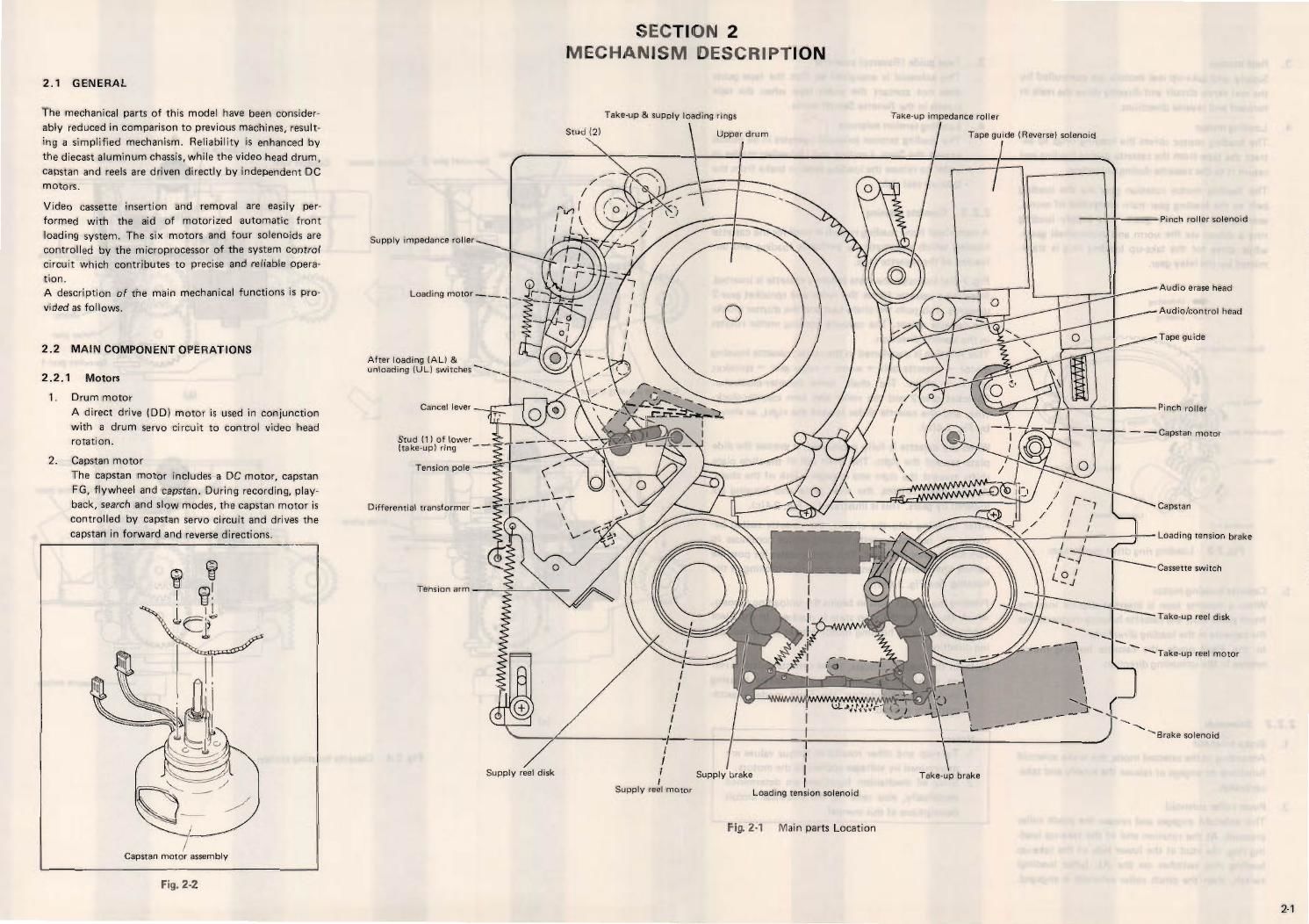
2.1 GENERAL

The mechanical parts of this model have been consider
ably reduced in comparison to previous machines, result-
ing a simplified mechanism. Reliability is enhanced by
the diecast aluminum chassis, while the video head drum,
capstan and reels are driven directly by independent DC
motors.

Video cassette insertion and removal are easily per-
formed with the aid of motorized automatic front
loading system. The six motors and four solenoids are
controlled by the microprocessor of the system control
circuit which contributes to precise and reliable opera-
tion.

A description of the main mechanical functions is pro-
vided as follows.

2.2 MAIN COiMPONENT OPERATIONS

2.2.1 Motors

1. Drum motor
A direct drive (DD) motor is used in conjunction
with a drum servo circuit to control video head
rotation,

2. Capstan motor
The capstan motor includes a DC motor, capstan
FG, flywheel and capstan. During recording, play-
back, search and slow modes, the capstan motor is
controlled by capstan servo circuit and drives the
capstan in forward and reverse directions.

Capstan motor assembly

Fig. 2-7.

SECTION 2
MECHANISM DESCRIPTION

Take-up & supply loading rings TEkE-UP impedance roller

Srua l2) Upper drum


Supply impedance roller
\

Loading motor _;

After loading [AL] &
unloading (UL) switches \\\\

Cancel lever

Stud (1) oflower
(take-up) ring
Tension pole

Differential transformer --

Tension arm

C9

uvuwtf! u-
x ,M

Supply reel disk I Supply brake Take-up brake

I
|
|
r l i
|
I I
Supply reel motor

Loading tension solenoid

Fig. 2-1 Main parts Location

Tape guide (Reverse) solenoid

-Pinch roller solenoid

/ Audio erase head
/Audio/control head

/Tape guide

-=Pinch roller

- - HCapstan motor

\ Capstan

\ Take-up reel motor

\ Brake solenoid

2-1

Page 2

3.

Woiniwheel geav

Reel motors

Supply and take-up reel motors are controlled by
the reel servo circuit and directly drive the reels in
forward and reverse directions.

Loading motor

The loading motor drives the loading rings to ex-
tract the tape from the cassette during loading and
return it to the cassette during unloading.

The loading motor rotation goes via the loading
belt to the loading gear train Composed of worm,
wormwheel and relay gears. The supply loading
ring is driven via the worm and wormwheel gears,
while drive for the take-up loading ring is trans-
mitted by the relay gear.

4- .Unioading
fie . Loading

Relay my

0' m gleal

/ Loading motor
Loading txrlr

Fig. 2-3 Loading ring drive mechanism

Cassette housing motor

When a cassette tape is inserted slightly into the
front panel slot, the cassette housing motor moves
the cassette in the loading direction.

In the Eject mode, the cassette housing motor
rotates in the unloading direction.

2.2.2 Solenoids

1.

2-2

Brake solenoid

According to the selected mode, the brake solenoid
functions to engage or release the supply and take
up brakes.

Pinch roller solenoid

This solenoid engages and release the pinch roller
pressure. At the rotation end of the takeup load-
ing ring, the stud at the lower side of the take-up
loading ring switches on the AL laiter loading)
switch, then the pinch roller solenoid is engaged.

3. Tape guide (Reverse) solenoid
This solenoid is energized so that the tape guide
does not contact the video tape when the tape
travels in the Reverse Search mode.

4. Loading tension solenoid
The loading tension solenoid operates in all modes
except the Stop, Loading and Unloading modes in
order to release the loading tension brake from the
take-up reel disk.

2 .2 . 3 Cassette housing

A motorized front loading system is used for the cassette
housing which automatically performs loading and un-
loading of the cassette tape.

Fig. 24(3) indicates the state before a cassette is inserted.
Inserting a cassette forces the roller and sprocket gear-2
upwards. This pulls the chain taut and the shutter blocks
the cassette sensor. The cassette housing motor rotates
in the loading direction.

This rotation is transferred in the route: cassette housing
motor -> cassette belt -> worm v> relay gear -> sprocket
gear-1 -> chain. The chain turns counterclockwise.
Sprocket gear-2 and the roller also turn counter-clock-
wise, and the cassette slides toward the right, as shown
by Fig. 2-4lb).

When the cassette is fully positioned, it presses the slide
plate toward the right. The chain pin of the slide plate
shifts toward the right and engages a link of the chain.
As the chain rotates, the slide plate and housing are
lowered by gears, This is illustrated in Fig. 2-4lcl.

After lowering into the chassis, the cassette switch be-
comes on, but the cassette housing motor continues to
turn for another 300 msec. This compensates for possible
switch timing error and ensures proper positioning of the
housing. See Fig. 2-4id).

Pressing the EJECT button begins the unloading process,
which starts after the stop state is reached. In the Eject
mode, the cassette housing motor rotates in the unload-
ing direction.

Note: in the loading process, if the cassette switch is not
on within 5 seconds after the cassette housing
motor begins rotating, the Eject mode is auto-
matically entered.

Notes:

1. Take-up and other rotational torque values are
determined by voltages applied to the motors.

2. Since all mechanism functions are determined
electrically, also refer to the electrical circuit

descriptions of this manual.

Chain

Cassette housi ng motor

Roller

(a)

lcl

Sprocket gear-2 Cassette sensor Cassette tape l - Shun?"

Cassette belt i

«cu
L-s


W [bl

Cassette door

Slide plate
_ -+>
l
egg -
Cassette switch
it!)
Fig. 24 Cassette housing system