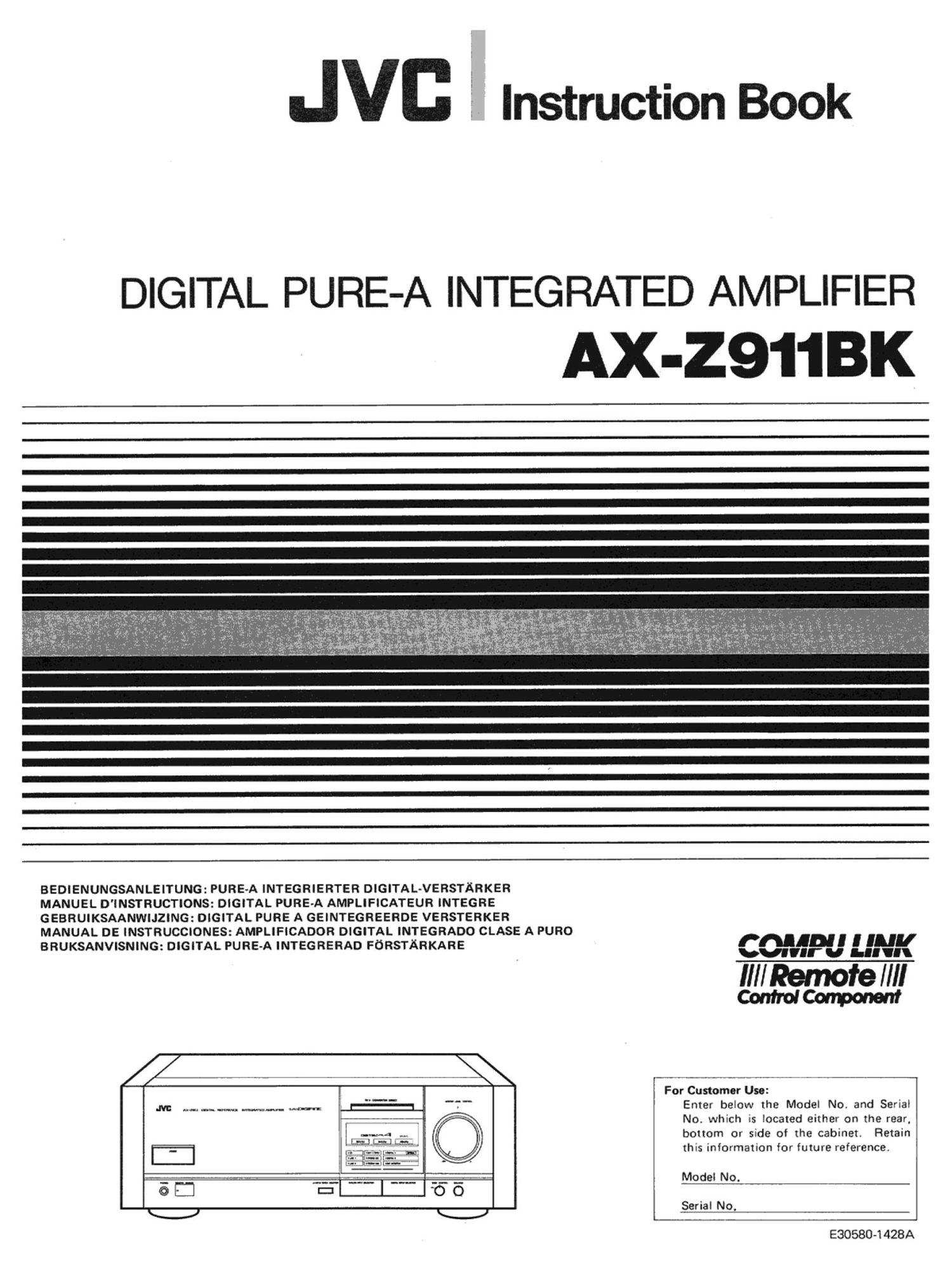
Jvc AXZ 911 BK Owners Manual

This is the 40 pages manual for Jvc AXZ 911 BK Owners Manual.
Read or download the pdf for free. If you want to contribute, please mail your pdfs to info@audioservicemanuals.com.

Page: 1 / 40
left right
Jvc AXZ 911 BK Owners Manual

Extracted text from Jvc AXZ 911 BK Owners Manual (Ocr-read)


Page 1

Instruction Book

DIGITAL PURE-A INTEGRATED AMPLIFIER

X-2911BK

BEDIENUNGSANLEITUNG: PURE-A INTEGRIERTER DIGITAL-VERSTARKER

MANUEL D'INSTRUCTIONS: DIGITAL PURE-A AMPLIFICATEUR INTEGRE
GEBRUIKSAANWIJZING: DIGITAL PURE A GEINTEGREERDE VERSTERKER

MANUAL DE INSTRUCCIONES: AMPLIFICADOR DIGITAL INTEGRADO CLASE A PURO
BRUKSANVISNING: DIGITAL PURE-A INTEGRERAD FDRSTARKARE

/ \

.M: ..-............ MW. moan: =I

um-A .-
L-_~_.I.l.-.~_I E9...
- [73' ffiv'r-jII-«i 'mt
' [--- ._. .-.. '
g I.» _.;.___,___

PM! I I [All]
war 0 I." 'l

IIII Remote IIII
ControICammem

For Customer Use:
Enter below the Model No. and Serial
No. which is located either on the rear,
bottom or side of the cabinet. Retain
this informaxion for future reference.

Model No.

Serial No.

E30580-I 428A

Page 2

IMPORTANT (In the United Kingdom)
Mains Supply (AC 240V N, 50 Hz only)

IMPORTANT

Do not make any connection to the Larger Terminal coded E or
Green. The wires in the mains lead are coloured in accordance
with following code:

3 Blue to N(Neutral) or Black
Brown to L(Live) or Red
If these colours do not correspond with the terminal
identifications of your plug, connect as follows:
Blue wire to terminal coded N(Neutral) or coloured Black.

Brown wire to terminal coded L(Live) or coloured Red.
If in doubt -- consult a competent electrician.

THIS UNIT IS PRODUCED TO COMPLY WITH
DIRECTIVE 82/499/EEC.

DIESES GERAT ENTSPRICHT EEC-RICHTLINIE
82/499.

CET APPAREIL A ETE FABRIQUE POUR El'RE
CONFORME A LA DIRECTIVE CEE NUMERO
82/499.

DENNA APPARAT AR TILLERKAD SA ATT
DIREKTIVEN 82/499/EEC UPPFYLLS

INFORMATION (For U.S.A.)

This equipment generates and uses radio Irequency energy and it not
installed and used property. that is. in strict accordance with the
manufacturer's instructions. may cause interterence to radio and television
reception. It has been type tested and found to comply with the limits tor a
Class B computing device in accordance With the specifications in Subpart
J of Part 15 ol FCC Rules. which are designed to provide reasonable
protection against such interterence in a residential installation. However.
there is no guarantee that interference will not occur in a particular
installation. It this equipment does cause interterence to radio or television
reception, which can be determined by turning the eqUipment oil and on.
the user is encouraged to try to correct the interference by one or more ot
the following measures:

Reorient the receiving antenna;

Relocate this equipment with respect to the receiver;

Move this equipment away from the receiver;

Plug this equipment into a different outlet so that this equipment and

receiver are on different branch circuits.
If necessary. the user should consult the dealer or an experienced
radio/television technician for additional suggestions. The user may lind
the tollowing booklet prepared by the Federal Communications
Commission helptul:

"How to Identity and Resolve Radio-TV lntenerence Problems". This
booklet is available trom the US Government Printing Office. Washington.
00.. 20402. Stock No.004-000-00345-4.

IMPORTANT (CANADA ONLY/CANADA
SEU LEMENT)

CAUTION: TO PREVENT ELECTRIC SHOCK DO NOT USE
THIS (POLARIZED) PLUG WITH AN EXTENSION CORD,
RECEPTACLE OR OTHER OUTLET UNLESS THE BLADES
CAN BE FULLY INSERTED TO PREVENT BLADE EXPOSURE

ATTENTION: POUR PREVENIR LES CHOCS ELECTRIOUES
NE PAS UTILISER CETTE FICHE POLARISEE AVEC UN
PROLONGATEUR, UNE PRISE DE COURANT 0U UNE
AUT-RE SORTIE DE COURANT, SAUF SI LES LAMES PEU-
VENT ETRE INSEREES A FOND SANS EN LAISSER AUCUNE
PARTIE A DECOUVERT

ATTENTION

CAUTION

To reduce the risk of electrical shocks, fire,

etc.:

1. Do not remove screws, covers or cabinet.

2. Do not expose this appliance to rain or
moisture.

ACHTUNG

Zur Verhinderung von elektrischen Schlagen

Brandgefahr usw.:

1. Kaine Schrauben lesen oder Abdeckungen
entfernen und nicht das Gehause offnen.

2. Dieses Gerat weder Regen noch Feuchtigkeit
ausetzen.

Afin d'éviter tout risque de commotion élec-

trique, d'incendie, etc.:

1. Ne pas enlever les vis ni les panneaux et ne
pas ouvrir le coffret de Iappareil.

2. Ne pas exposer l'appareil a la pluie ni a
Ihumidité.

Thank you for purchasing this JVC product.
Before you begin operating this unit, please
read the instructions carefully to be sure you
get the best possible performance.

If you have any question, consult your JVC
dealer.

Bielen Dank fiir den Kauf dieses JVCProdukts.
Bitte lesen Sie-diese Bedienungsanleitung sorg-
faltig. bevor Sie dieses Gerat in Betrieb nehmen,
um die baste Leistung zu erhalten.

Falls Sie Fragen haben, wenden Sie sich bitte an
lhren JVC-Fachhandler.

Tour nos compliments pour vous étre procuré
cet appareil de JVC.

Pour que vous puissiez obtenir les meilleures
performances possibles. nous vous recom-
mandons de lire attentivement la présente
notice demploi avant de commencer a utiliser
votre nouvel appareil.

En cas de question, consultez votre revendeur
JVC.

Page 11

0 REMOTE SENSOR
This sensor receives the signal transmitted
from the remote control unit. When a signal
is being received the indicator will light.

6 OAT 2/TAPE 2 MONITOR
The indicator will light when this button is
pressed. It is possible using this button to
monitor a DAT deck, cassette deck or SEA
graphic equalizer, connected to the DAT 2/
TAPE 2 terminals. If the button is pressed
again monitoring will stop.

0 ANALOG INPUT SELECTOR

When this button is pressed the areas in the
display section above the button will light
up in sequence. You can change to different
analog signal sources using this button.
While the button is being pressed the names
of the sources will change in sequence.

(CD) -t (LINE 1) -> (LINE 2) -> (DAT ll
FTAPE 1) -. IPHONO MM or MC) -l

([9 DIGITAL INPUT SELECTOR

When this button is pressed the areas in the

display section above the button will light

up in sequence. You can change to different

digital signal sources, using this button.

While the button is being pressed the names

of the sources will change in sequence.
(DIGITAL) (OPTICALl) -* (DIGITAL
2) - (DAT MONITOR + DIGITAL 1) a
(DAT MONITOR + DIGITAL 2) -|

DIGITAL INPUT

A digital signal source connected to the
amplifiers DIGITAL INPUT terminal will be
processed by the DIGITAL PURE A circuit
(For details please read the explanation on
page 19.) enabling you to enjoy optimal A
CLASS sound production.

0 Source indicator
The name of the source selected by using
either the ANALOG INPUT SELECTOR or
the DIGITAL INPUT SELECTOR will be
displayed in the respective display sections.

(E BASS CONTROL
When music volume is turned down the hu-
man ear tends to become less aware of bass
sound. This can be compensated for by
adjusting the bass control knob so that you
can enjoy powerful has even at low sound
level.

(9 BALANCE
This knob adjusts the volume balance be-
tween the left and right speakers.
Normally it is set to the center. [When D/A
CONVERTER DIRECT is being used this
knob will not operate.)

0 OPERATE indicator
When lit. this indicates that a digital input
is being received and the DIGITAL PURE A
circuit is operating.

0 Fembedienungssensor (REMOTE SENSOR)
Dieser Sensor emOfangt das von der Fernbe-
dienungseinheit gesendete Signal. Bei Signal-
empfang Ieuchtet die Anzeigelampe auf.

G) DAT 2/TAPE 2 MONITOR

Die Anzeigelampe Ieuchtet auf. wenn diese
Taste gedriickt wird. Mit Hilfe der Taste
(as: sich der Betrieb eines DA-Tonband-
gerats. eines Kassettendecks oder eines SEA-
Graphic-Equalizers mit der Monitor-Funk-
tion kontrollieren, wenn diese Gerate an die
DAT 2/TAPE 2-Anschlul3buchsen ange-
schlossen sind. Bei erneutem Tastendruck
wird die Kontrollfunktion ausgeschaltet.

0 wahler fiir Analogsignalquellen (ANALOG
INPUT SELECTOR)
Bei Tastendruck Ieuchten die Felder im
Display fiber der Taste der Reihe nach auf.
Mit der Taste Iassen sich dann verschiedene
Analogsignalquellen wahlen. Wéihrend die
Taste gedriickt wird, wechseln die Namen
der Signalquellen nacheinander.

(CD) -> (LINE 1) -> (LINE 2) - (DAT 1/

FTAPE 1) -* (PHONO MM oder MC) 1

@Wfihler fiir Digitalsignalquellen (DIGITAL
INPUT SELECTOR)
Bei Tastendruck Ieuchten die Felder im Dis-
play I'iber der Taste der Reihe nach auf. Mit
der Taste Iassen sich dann verschiedene
Digitalsignalquellen wahlen. wahrend die
Taste gedriickt wird, wechseln die Namen
der Signalquellen nacheinander.
(DIGITAL) (OPTICALH -t (DIGITAL
2) -* (DAT MONITOR + DIGITAL ll -*
(DAT MONITOR + DIGITAL 2) -I

Digital-AnschluISklemme (DIGITAL INPUT)
Eine an die DIGITAL INPUT-Anschluf3~
buchse des Verstarkers angeschlossene digi-
tale Signalquelle wird fiber den DIGITAL
PURE-A-Schaltkreis verarbeitet. was hOch-
ste Klangqualitat der Verstarkerklasse A
sichert. (Einzelheiten hierzu finden Sie auf

Seite 19.)

m Signalquellenanzeige
Der Name der mittels ANALOG INPUT
SELECTOR oder DIGITAL INPUT SE-
LECTOR gewahlten Signalquelle wird in
den jeweiligen Display-Feldern angezeigt.

® Baaausgleich
Bei niedriger Lautstarke wird das mensch-
liche 0hr tieferen Tdnen gegent'jber unemp-
findlich. Ein Ausgleich ist mit Hilfe des
balSreglers méglich. so dal3 auch bei niedri-
gen Lautstarkewerten noch kraftige Basse
hérbar sind.

0 BALANCE

Dieser Knopf dient zur Regelung der Laut-
starkebalance zwischen den Lautsprechern
rechts und links. Normalerweise sollte der
Reglerknopf in der Mittenposition stehen.
(Bei Verwendung von D/A CONVERTER
DIRECT ist die Knopffunktion ausgeschal-
tet.)

@OPE RATE Anzeige (OPERATE)
Wéihrend diese Anzeige aufleuchtet. wird
eine Digital-Signalquelle empfangen. und der
DIGITAL PURE-A-Schaltkreis ist aktiv.

-11-

0 Detecteur de telecommunde (REMOTE

SENSOR)

Ce détecteur reCOit le signal transmis du
boitier de télécommande. Pendant qu'un
signal est recu, Ie témoin reste allumé.

Q Comrble de magnetophone audionumerique
Zlbende 2 (DAT 2/TAPE 2)
Le témoin s'allume Iorsque cette tauche est
enfoncée. A laide de cette touche, il est
possible de controéler un enregistreur audio-
numérique. une platine a cassettes ou un
égaliseur graphique SEA raccordé aux
bornes de magnétophone audionumérique
2/bande 2 (DAT 2/TAPE 2). Si cette touche
est de nouveau enfoncée, Ie contréle
s'arréte.

9 Sélecteur d'entrée analogique

(ANALOG INPUT SELECTOR)
Lorsque cette touche est enfoncée, Ia zone
de section d'alfichage audesws de la touche
s'allume en sequence. Il est possible de
passer en diffe'rentes sources de signal
analogique s I'aide de cette touche. Pendant
que cette (Ouche est enfoncée, les designa-
tions des sources apparaissent en sequence
Iune apres Iautre.

(CD) -' (LINE 1) -* (LINE 2) -> (DAT 1/
r TAPE 1) _. (PHONO MM ou MC) 1

w Sélecteur d'entrée numérique
(DIGITAL INPUT SELECTOR)
Lorsque cette touche est enfoncée, la zone
de section dalfichage au-dessus de la
t0uche sallume en sequence. ll est possible
de passer en différentes sources de signal
numérique a laide de cette touche. Pendant
que cette touche est enfoncée. les désigna-
tions des sources apparaissent en sequence
I'une apres l'autre.
(DIGITAL 1 (OPTICALI) -* (DIGITAL
2) -> (DAT MONITOR + DIGITAL 1) -r
(DAT MONITOR + DIGITAL 2) 1

Entrée numérique

Une sOurce de signal numerique raccordée
a la borne d'entrée numérique (DIGITAL
INPUT) de I'amplificateur sera traitée par Ie
circuit DIGITAL PURE A (pour plus de
détails, se référer .a Iexplication de la page
19.). permettant ainsi la production sonore
optimale de CLASS A.

@ Indicateur de source
La designation de la source sélecrionnée a
I'aide du sélecteur d'entrée analogique
(ANALOG INPUT SELECTOR) ou du
sélecteur dentrée numérique (DIGITAL
INPUT SELECTOR) sera affichée dans les
sections d'affichage respectives.

(E Contrdle de basses (BASS CONTROL)
Lorsque le volume de musique est reduit. )es
oreilles humaines ont tendance a devenir
plus sensibles aux basses. Cela peur étre
compensé en réglant le bouton de contréle
de basses pour jouir des basses puissantes
meme au niveau sonore réduit.

(E Balance (BALANCE)
Ce bouton permet de régler la balance entre
les hautparleurs de gauche et de droite.
Normalement. il est placé sur la position
centrale. (Pendant que le bouton D/A
CONVERTER DIRECT est utilise. ce

bouton ne fonctionne pas.)

w Indieeteur d'opération
(OPERATE)
Lorsquil est allumé, ce témoin indique
qu'une entree numérique est en cours de
reception et que la cirCUit DIGITAL PURE
A est en fonction.

Page 12

0 REMOTE SENSOR
This sensor receives the signal transmitted
from the remote control unit. When a signal
is being received the indicator will light.

9 OAT 2/TAPE 2 MONITOR
The indicator will light when this button is
pressed. It is possible using this button to
monitor a DAT deck, cassette deck or SEA
graphic equalizer, connected to the DAT 2/
TAPE 2 terminals. If the button is pressed
again monitoring will stop.

9 ANALOG INPUT SELECTOR

When this button is pressed the areas in the
display section above the button will light
up in sequence. You can change to different
analog signal sources using this button.
While the button is being pressed the names
of the sources will change in sequence.

(CD) -r (LINE 1) -* (LINE 2) - (DAT 1/
FTAPE I) -> (PHONO MM or MC) 1

0 DIGITAL INPUT SELECTOR

When this button is pressed the areas in the

display section above the button will light

up in sequence. You can change to different

digital signal sources, using this button.

While the button is being pressed the names

of the sources will change in sequence.
(DIGITAL I (OPTICAL)) ~r (DIGITAL
2) -* (DAT MONITOR + DIGITAL I) ->
(DAT MONITOR + DIGITAL 2) _)

DIGITAL INPUT

A digital signal source connected to the
amplifiers DIGITAL INPUT terminal will be
processed by the DIGITAL PURE Acircuit
(For details please read the explanation on
page 19.) enabling you to enjoy Optimal A
CLASS sound production.

0 Source indicator
The name of the source selected by using
either the ANALOG INPUT SELECTOR or
the DIGITAL INPUT SELECTOR will be
displayed in the respective display sections.

(2) BASS CONTROL
When music volume is turned down the hu-
man ear tends to become less aware of bass
sound. This can be compensated for by
adjusting the has control knob so that you
can enjoy powerful bass even at low sound
level.

IE BALANCE
This knob adjusts the volume balance be-
tween the left and right speakers.
Normally it is set to the center. (When D/A
CONVERTER DIRECT is being used this
knob will not operate.)

0 OPERATE indicator
When (it, this indicates that a digital input
is being received and the DIGITAL PURE A
circuit is Operating.

0 Fornbedienungssensor (REMOTE SENSOR)
Dieser Sensor eméf'angt das von der Fernbe-
dienungseinheit gesendete Signal. Bei Signal-
empfang Ieuchtet die Anzeigelampe auf.

9 DAT 2/TAPE 2 MONITOR

Die Anzeigelampe Ieuchtet auf. wenn diese
Taste gedriickt wird. Mit Hilfe der Taste
I58! sich der Betrieb eines DA-Tonband-
gerats, eines Kassettendecks Oder eines SEA-
Graphic-Equalizers mit der Monitor-Funk-
tion kontrollieren, wenn diese Gerate an die
DAT 2/TAPE 2-Anschlul3buchsen ange-
schlossen sind. Bei erneutem Tastendruck
wird die Kontrollfunktion ausgeschaltet.

9 Wihler fiir Analogsignalquellen (ANALOG
INPUT SELECTOR)
Bei Tastendruck Ieuchten die Felder im
Display (iber der Taste der Reihe nach auf.
Mit der Taste Iassen sich dann verschiedene
Analogsignalquellen wahlen. wahrend die
Taste gedriickt wird, wechseln die Namen
der Signalquellen nacheinander.

(CD) -> (LINE 1) -> (LINE 2) -* (DAT I!

FTAPE I) -> (PHONO MM oder MC) ]

@wsmer fiir Digitalsignalquellan (DIGITAL
INPUT SELECTOR)
Bei Tastendruck Ieuchten die Felder im Dis
play iiber der Taste der Reihe nach auf. Mit
der Taste lassen sich dann verschiedene
Digitalsignalquellen wahlen. wahrend die
Taste gedriickt wird. wechseln die Namen
der Signalquellen nacheinander.
(DIGITALI (OPTICAL)) ~+ (DIGITAL
2) -r (DAT MONITOR + DIGITAL I) -*
(DAT MONITOR + DIGITAL 2) -]

Digital-AnschluBklemme (DIGITAL INPUT)
Eine an die DIGITAL INPUT-Anschlufs-
buchse des Verstérkers angeschlossene digi-
tale Signalquelle wird fiber den DIGITAL
PURE-A-Schaltkreis verarbeitet, was hbch-
ste Klangqualitét der Verstarkerklasse A
sichert. (Einzelheiten hierzu finden Sie auf
Seite 19.)

Q Signalquellenanzeige
Der Name der mittels ANALOG INPUT
SELECTOR oder DIGITAL INPUT SE-
LECTOR gew'ahlten Signalquelle wird in
den ieweiligen Display-Feldern angezeigt.

® BaBausgIeich
Bei niedriger Lautstarke wird das mensch-
Iiche 0hr tieferen Tdnen gegeniiber unemp-
findlich. Ein Ausgleich ist mit HiIfe des
balsreglers mdglich, so daB auch bei niedri~
gen Lautstarkewerten noch kr'a'ftige Basse
h6rbar sind.

ID BALANCE

Dieser Knopf dient zur Regelung der Laut.
starkebalance zwischen den Lautsprechern
rechts und links. Normalerweise sollte der
Reglerknopf in der Mittenposition stehen.
(Bei Verwendung von D/A CONVERTER
DIRECT ist die Knopffunktion ausgeschal-
tet.)

IIIOPERATE Anzeige (OPERATE)
wahrend diese Anzeige aufleuchtet, wird
eine Digital-Signalquelle empfangen, und der
DIGITAL PURE-A-Schaltkreis ist aktiv.

-11-

0 Détectour do télécommande (REMOTE
SENSOR)
Ce détecteur recoit Ie signal transmis du
boitier de télécommande. Pendant quun
signal est recu, Ie témoin reste allumé.

9 Oontrdle do magnetophone audionumérique
Zlbande 2 (DAT ZITAPE 2)
Le témoin s'allume lorsque cette touche est
enfoncée. A Iaide de cette touche, il est
possible de controéler un enregistreur audio-
numérique, une platine a cassettes do on
égaliseur graphique SEA raccordé aux
bornes de magnétophone audionumérique
2/bande 2 (DAT 2/TAPE 2). Si cette touche
est de nOuveau enfoncée, le contréle
s'arréte.

0 selecteur d'entrée analogique

(ANALOG INPUT SELECTOR)
Lorsque cette touche est enfoncée. Ia zone
de seCIion d'affichage audessus de la touche
sallume en sequence. II est possible de
passer en différentes sources de signal
analogique a Iaide de cette touche. Pendant
que cette touche est enfoncée, Ies designa-
tions des sources apparaissent en sequence
lune apres l'autre.

(CD) ~ (LINE I) -* (LINE 2) -r (DAT 1/
r TAPE 1) -> (PHONO MM ou MC) :)

® Sélecteur d'entrée numérique
(DIGITAL INPUT SELECTOR)
Lorsque cette touche est enfoncée. Ia zone
de section d'alfichage audessus de la
touche sallume en sequence. Il est possible
de passer en différentes saurces de signal
numérique a I'aide de cette touche. Pendant
que certe touche est enfoncée, Ies designa-
tions des sources apparaissent en sequence
Iune aprés l'autre.
(DIGITALI (OPTICALI) -> (DIGITAL
2) -' (DAT MONITOR + DIGITAL I) -r
(DAT MONITOR + DIGITAL 2) 1

Entree numérique

Une source de signal numérique raccordée
a la borne dentrée numérique (DIGITAL
INPUT) de I'amplificateur sera traitée par la
circuit DIGITAL PURE A (pour plus de
détails, se référer a l'explication de la page
(9.). permettant ainsi la production sonore
optimale de CLASS A.

0 Indicateur do source
La designation de la source sélectionnée a
l'aide du sélecteur d'entrée analogique
(ANALOG INPUT SELECTOR) ou du
sélecteur d'entrée numérique (DIGITAL
INPUT SELECTOR) sera atfichee dans les
sections d'affichage respectives.

ID ContrOIe do basses (BASS CONTROL)
Lorsque Ie volume de musique est réduit, Ies
oreilles humaines ont tendance a devenir
plus sensibles aux basses. Cela peut étre
compensé en réglant le bouton de contréle
de basses pour iouir des basses puissantes
meme au niveau sonore réduit.

IF.) Balance (BALANCE)
Ce bouton permet de régler Ia balance entre
Ies hautparleurs de gauche et de droite.
Normalement. il est placé sur la position
centrale. (Pendant que le bouton D/A
CONVERTER DIRECT est utilise, ce
bouton ne fonctionne pas.)

G Indicateur d'opération
(OPERATE)
Lorsquil est allumé, ce témoin indique
qu'une entree numérique est en cours de
reception et que la circuit DIGITAL PURE
A est en fonction.