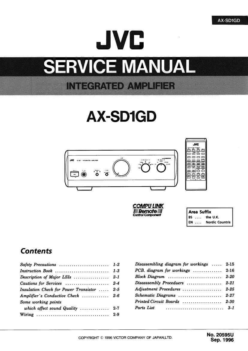
Jvc AX SD1GD Service Manual

This is the 102 pages manual for Jvc AX SD1GD Service Manual.
Read or download the pdf for free. If you want to contribute, please mail your pdfs to info@audioservicemanuals.com.

Page: 1 / 102
left right
Jvc AX SD1GD Service Manual

Extracted text from Jvc AX SD1GD Service Manual (Ocr-read)


Page 1

AXSBIGD

Jvc
SAUAVERVICEML

AX-SD1GD

.M: umv «my-mm


L._I
rnunu I [All
w
finanxfleflfl AnaSufik
mm as the UL
EN . . . . Nordic Countris
Contents
Safety Precautions ........................ 1-2 Disassembling diagram for workings ..... 2-15
Instruction Book ,,,,,,,,,,,,,,,,,,, 1-3 PCB. diagram for workings .............. 2-16
Description of Major LSIs . . ........ 2-1 Block Diagram ............... 2-20
Cautions for Services ..................... 2-4 Disasssembly Proceduers ........ 2-21
Insulation Check for Power Transistor ..... 2-5 Adjustment Procedures ............ . 2-25
Amplifier s Conductive Check ............. 2-6 Schematic Diagram ..................... 2-27
Some working points Printed Circuit Boards ................... 2-30
which affect sound Quality .............. 2-7 Parts List ............................ 3-1
Wiring ................................... 2-9
No.20595U

COPVRIGHT © 1996 VICTOR COMPANY OF JAPAN.LTD.

Sep.1996

Page 2

- Safety Precautions

1.The design of this product contains special hardware and many circuits and components
specially for safety purposes. For continued protection, no changes should be made to the
original design unless authorised in writing by the manufacturer. Replacement parts must
be identical to those used in the original circuits.

2. Any unauthorised design alterations or additions will void the manufacturer's guarantee;
furthermore the manufacturer cannot accept responsibility for personal injury or property
damage resulting therefrom.

3. Essential safety critical components are identified by (A) on the Parts List and by shading
on the schemati5,and must never be replaced by parts other than those listed in the
manual. Please note however that many electrical and mechanical parts in the product have
special safety related characteristics. These characteristics are often not evident from visual
inspection . Parts other than specified by the manufacturer may not have the same safety
characteristics as the recommended replacement parts shown in the Parts List of the service
manual and may create shock,fire,or other hazards.

4. The leads in the products are routed and dressed with ties, clamps, tubings, barriers and
the like to be separated from live parts, high temperature parts, moving parts and/or sharp
edges for the prevention of electric shock and fire hazard. When service is required, the
original lead routing and dress should be observed, and it should be confirmed that they
have been returned to normal, after re-assembling.

Warning

1. Service should be performed by qualified personnel only.
2. This equipment has been designed and manufactured to meet international safety standards.

3. It is the legal responsibility of the repairer to ensure that these safety standards are
maintained.

4. Repairs must be made in accordance with the relevant safety standards.
5. It is essential that safety critical components are replaced by approved parts.
6. If mains voltage selector is provided, check setting for local voltage.

1-2

Page 46

AX-SD1GD

13. Pre-Drive PCB (ENH-282-4) removal was ® © /@\ ®

1) Disassemble the rear panel ass'y. \ .

2) Remove 2 plastic rivets ® fastening the pre- © <1 ,_>©
drive PCB. \. ENH-282-4 , a

3) Pull out the master volume knob. - _

4) Remove nut fastening master volume shaft. In H n l- . Ill-l:

5) Pull out the master volume shaft from joint . . . .
assy. Trans Trans

6) Remove the joint sssy.

4) Disconnect the connectors
(CN441,CN442,CN443,CN444,CN447,CN448,
CN971,CN972,CN831,0N832). Joint assy
The PCB. can be open to be handled.
Unsolder other wires and connectors if
necessary.

Fig-10. Upper side

14. Regulator PCB (ENH-282-3) removal
1) Remove the pre-drive PCB.

2) Remove 11 screws © fastening the volume
bracket and regulator PCB to remove its.

(Unsolder other wires and connectors which are
connected with the PCB. if necessary.)

fl Bushing Whaser
15. Input PCB (ENH-282-5) removal

1) Remove the phono EQ PCB. Fig.-11 Rear side
2) Disassemble the rear panel assy.

3) Disconnect the connectors (CN842,CN381,CN101,CN301).

4) Remove 6 screws ® fastening the input PCB.

5) Remove 3 plastic rivets ® fastening the shield plate and input PCB to remove its.

Fig.-12 Rear panel assy

2-24

Page 48

AX-SD1GD

I NOTICES BEFORE POWERING

AC primary voltage is set amp.s rated voltage.

I ADJUSTMENT PROCEDURES
* It varies sliqhtly dependinq on Q301 and 0302.
1. Offset voltage Adjustment (No load and No signal)
1) Measurement points Speaker terminal
2) Adjustment points Lch:VR313 Rch1VR314

3) Adjustment Procedures

(1) Turn ON. ON to set it PRESENCE 3 and adjust VR313 and VR314 so that DC output
from speakers becomes 0i10mV.

(2) Keep the unit for cooling down after the adjustment. Turn the unit ON and check that
DC output is within i50mV.

2. Main Amp Idling Current Adjustment (No load and No signal)

1) Measurement points
Lch : Between pins (D and ®of TP471, between pins® and ®of TP471
Rch : Between pins CD and @0f TP472, between pins® and ®of TP472
2) Adjustment points Lch : VR485 Rch2VR486

3) Adjustment Procedures
(1) Set the volume control to minimum during this adjustment.
(2) Turn R485 and R486 fully counterclockwise before the power is switch on,

(3) Turn the power 0N without load and signal while the top cover and the side panel
assembled with the unit.

(4) Check that there is no fault after the power 0N and rotate VR485 and VR486
clockwise for its one third so that Lch and Rob can meet each target value described
below after its specified time.

And, check the deviation between Lch and Rob is within 20%.

(Target value for adjustment)

Lch=3.1mV (After 258ec.)
Rch=2.2mV (After 35sec.)

2-26