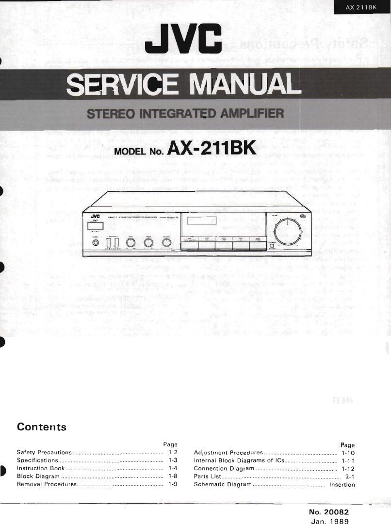
Jvc AX 211 BK Service Manual

This is the 25 pages manual for Jvc AX 211 BK Service Manual.
Read or download the pdf for free. If you want to contribute, please mail your pdfs to info@audioservicemanuals.com.

Page: 1 / 25
left right
Jvc AX 211 BK Service Manual

Extracted text from Jvc AX 211 BK Service Manual (Ocr-read)


Page 1

SERV CE MANUAL

6
i
,
s
{

Contents

Page
Safety Precautions .......................................................... 1-2
Specifications ..... 13

M
1-8
1.9

Instruction Book.
Block Diagram .......
Removal Procedures.

Adjustment Procedures...
Internal Block Diagrams of ICs
Connection Diagram ..................
Parts List ...................
Schematic Diagram

. Insertion

No. 20082
Jan. 1989

Page 2

l AX-2118K

rSafety Precautions ,

l.

The design of this product contains special hardware and many circuits and components specially for safety purposes.
For continued protection, no changes should be made to the original design unless authorized in writing by the
manufacturer. Replacement parts must be identical to those used in the original circuits, Service should be per-
formed by qualified personnel only.

. Alterations of the design or circuitry of the product should not be made. Any design alterations of the product

should not be made, Any design alterations or additions will void the manufacturers warranty and will further
relieve the manufacturer of responsibility for personal iniury or property damage resulting therefrom.

. Many electrical and mechanical parts in the product have special safety-related characteristics. These characteristics

are often not evident from visual inspection nor can the protection afforded by them necessarily be obtained by
using replacement components rated for higher voltage, wattage, etc. Replacement parts which have these special
safety characteristics are identified in the Parts List of Service Manual. Electrical components having such features
are identified by shading on the schematics and by (A) on the Parts List in the Service Manual. The use of a sub-
stitute replacement which does not have the same safety characteristics as the recommended replacement part shown
in the Parts List of Service Manual may create shock, fire, or other hazards.

. The leads in the products are routed and dressed with ties, clamps, tubings, barriers and the like to be separated from

live parts, high temperature parts, moving parts and/or sharp edges for the prevention of electric shock and fire hazard.
When service is required, the original lead routing and dress should be observed, and it should be confirmed that they
have been returned to normal, after re-assembling.

. Leakage current check (Electrical shock hazard testing)

After re-assembling the product, always perform an isolation check on the exposed metal parts of the product
[antenna terminals, knobs, metal cabinet, screw heads, headphone iack, control shafts, etc.) to be sure the product
is safe to operate without danger of electrical shock.

Do not use a line isolation transformer during this check.

I Plug the AC line cord directly into the AC outlet. Using a "Leakage Current Tester", measure the leakage current
from each exposed metal part of the cabinet, particularly any exposed metal part having a return path to the
chassis, to a known good earth ground. Any leakage current must not exceed 0.5 mA AC (r.m.s.).

o Alternate check method
Plug the AC line card directly into the AC outlet. Use an AC voltmeter having 1,000 ohms per volt or more sensi-
tivity in the following manner. Connect a 1,500 $2 10 W resistor paralleled by a 0.15 uF AC-type capacitor be-
tween an exposed metal part and a known good earth ground.

Measure the AC voltage across the resistor with the AC VOLTMEYER
AC voltmeter. @ (Having 1000 ohms/volt,

of more sensutivrty.)
Move the resistor connection to each exposed metal
part, particularly any exposed metal part having a
return path to the chassis, and measure the AC volt-
age across the resistor. Now, reverse the plug in the Place this mobs
AC outlet and repeat each measurement. Any voltage w» on each exposed
measured must not exceed 0.75 VAC (r.m.s.). This I5000 OW metal Part
corresponds to 0.5 mA AC (r.m.s.).

0.15 a; At: m2:

Good earth ground

manure--

~Warning

. This equipment has been designed and manufactured to meet international safety standards.

. it is the legal responsibility of the repairer to ensure that these safety standards are maintained.
. Repairs must be made in accordance with the relevant safety standards.

. It is essential that safety critical components are replaced by approved parts.

. If mains voltage selector is provided, check setting for local voltage,

1-2

(No. 20082)

Page 5

0 BASS
Turn clockwise tu boast bass response and
counterclackwse to decrease it.

o THEBLE
Turn clockwise to boost treble response and
counterclockwtse to decrease itr

0 BALANCE
Use to adjust the balance between the left
and right speakers.

3 SOURCE INDICATOR
By pressing the buttons 9 r G respective
LEDs light up. They also llght up when the
tape monitor button iS pressed. In this case,
the tape monitor button will have the priorlr
W.

OVOLUME
Turn Clockwise for louder sound.

0 Haadphunu )nck lFHONES)
Plug steren headphones into this jack lor
private listening.

9 TAPE MONITOR
Press in to listen to a tape played on a tape
deck connected to the TAPE (ermmals. If
your tape deck is a three-head deck, you can
manitor the sound that has lust been record
ed on the tape, To release [his function.
press l) again.

0 Aux
Frm to listen to the source connected to
the AUX terminals

0 TUNER
Press in to listen to broadcasts)

a CD
Press in to listen to a source connected to
the CD terminals.

0 PHONO
Press in to listen to records

0 LOUDNESS
Press this switch ON (-i tn compensate
for the ears different sensitivrty to saund at
low volumes,

9 EaBrcglev (BASS)
in! Unrzeigersinn warden die Tleltonfie
quenzen versmrkti gegen den Uhrzeigersinn
abgeschwacht

0 HéhenmgIMITREBLE)
lm Uhrzeigersmn warden die hohen Frer
quenzen verstakst gegen den Uhrzeigersmn
abgedampft.

o Balaucoregler (BALANCE)
Fur Balanceregelung zwischen linkem und,
recntem Lautsprecher

oauollanlnzligo (SOURCE INDICATOR)
Balm Drunken der Tasten 0 - ® , die
entsprecnenden LEDs )Euchten aui Sie
lauchten aui auch wenn die Band-Monitor
Taste gednickt wtrd In diesem Falle_ hat me
Band Monltnr-Taste den Vorrang

0 Lauutirke (VOLUME)
Zur Erholtung der Lautslarke im Uhrleigerr
sinn drehen

9 Kapfhbver-Buchn (PHONES)
Zum Anscmg van KooIhotem

0 Bind-Monitor [TAPE MONITOR)
Zur Wledergabe emer Bandauinahme Von
einem an den TAPErBuchsen angeschlos
senen TaperDeck Verfugt uas angesmlossene
Tape-Deck uber drei Tonkopfe. «5t Hinter
Dandkomrolle mogncn Nochrn-als dru'cken,
um diese Funk! on aDZuSchallen.

o AUX
Zum Anhoren der an die AUX.Klemmen
angeschlossenen Tonquelle diese Taste
dru'ckan

0 Tuna: (TUNER)
Zur Wtedergabe von
druckeu.

0 co
Zur Wienergaue emer an die CD-Klemmen
angeschlossenen Signaloueile druckeni

a Phone: lPHONO)
Zur Wtedergabe van Stralinlanen drucken

m Lautsxirkekonmr (LOUDNESS)
Diese Taste emschalzen in) um um: bei
niedriger Lautsrarke veranderte Emplmd-
lichkeit des Gehors zu komoensierén

Radiosendungen

AX211BK

9 Bases laAssl
Tourner dans le sens des aiguilles dune
montre pour augmenter la réponse ides bas-
565 et dans la sans contraire pour la diml
must

0 Aigufis ITREBLE)
Tourner dans le sens des aiguilles d'utte
monlre pour augmenter la rénonse des
algues at arms le sens Contralre pour la diml-
nuer.

9 Bel-m:- (BALANCE)
Utilisée pour régler la balance entre les hautr
parleurs cle gauche et de droite

0 Indicaleur is scarce lsounce INDICA-
TOR)
En enforcant les touchesg 7 w ,le LED
IESDECIWIS s'liluminent Elle: s'lllummenl
ausst lersque Ia [cache de comréle de bahde
est enfuncée. Dans ce cas, la tuucne de con
tréle cle barlde aura priorité

oVqumI (VOLUME)
La mum-3r darts le sens des aiguilles dune
montre pour augmenter le volume sonore.

0 Priu a: misqu- d'acouta (PHONES)
v raccorder un casque découte stereo Dour
une écou:e privée.

0 Cannot- on hands (TAPE MONITOR)
L'enfoncer pour écouter une bande Iue sur
une platme d'enregistrament raccovdee aux
bornes TAPE. Si votre Dietine a trois teres.
vous pouvez contréler le son qui went uétre
enregistré sur la Dande. Pour dégager cette
loncuon, enhancer cette muche a nouveau

O Aux
Aopuyer sur cette toucne pour ecouter la
Source raccordée aux bar Hes AU X.

Osmonesam (TUNER)
Lenloncer pour écouter des émissmns
radlodiflusées

Q Disque Iudionumriqne (co)
LenVoncer pour ecouter une source rac~
cordée aux bornes CD

0 Plume tnutmdisque (PHONO)
L'enloncer pour écouter des disques.

0 canton! (LOUDNESS)
Enluttcer ce commutateur in) Dour com-
penser la SenSIblllté dlfiérenle de l'oreille é
de taibles volumes

(No. 20082) 15