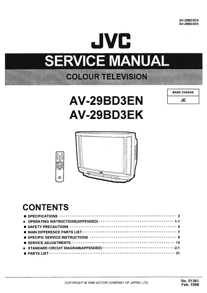
Jvc AV 29 BD 3 Service Manual

This is the 116 pages manual for Jvc AV 29 BD 3 Service Manual.
Read or download the pdf for free. If you want to contribute, please mail your pdfs to info@audioservicemanuals.com.

Page: 1 / 116
left right
Jvc AV 29 BD 3 Service Manual

Extracted text from Jvc AV 29 BD 3 Service Manual (Ocr-read)


Page 1

AV-2SBD3EN
AV-ZQBDSEK

JVC ¥
SERVICE MANUAL.

BASIC CHASSIS

AV-ZQBD3EN JE
AV-ZQBD3EK

CONTENTS

I SPECIFICATIONS ................................................................ 2
* OPERATING INSTRUCTIONS(APPENDED) ......................................... 1_1 .
I SAFETY PRECAUTIONS .......................................................... 4
I MAIN DIFFERENCE PARTS LIST ..................... . ............................. 7
I SPECIFIC SERVICE INSTRUCTIONS ............................................... 3
I SERVICE ADJUSTMENTS ........................................................ 13
* STANDARD CIRCUIT DIAGRAM(APPENDED) ....................................... 2.1
I PARTS LIST .................................................................... 31
No. 51361

OF J .
COPYRIGHT © 1998 VICTOR COMPANY APAN, LTD Feb. 1998

Page 36

AV-2QBDSEN
AV-2BBD3EK

SPECIFIC SERVICE INSTRUCTIONS

DISASSEMBLY PROCEDURE

REMOVING THE REAR COVER

1. Unplug the power cord.

2. Remove the 12 screws marked "X" as shown in the figure.
3. Withdraw the rear cover toward you.

REMOVING THE CHASSIS

0 After removing the rear cover.

1. Slightly raise the both sides of the chassis by hand and remove
the two claws under the both sides at the chassis from the front
cabinet.

2. Withdraw the chassis backward.

(If necessary, take off the wire clamp, connectors etc.)

REMOVING THE AV TERMI. BOARD

O Alter removing the rear cover.

1. While raising the claw marked A" ,remove the top of the AV
TERMI. Board slightly in the direction of arrow "B as shown in
Fig. 1.

2. Remove the claws marked c under the AV TERMI. Board ,
remove the AV TERMI. Board in the arrow direction marked D
as shown in Fig. 2

REMOVING THE CONTROL BASE

1. While pushing down the claws marked " E " ,remove the
CONTROL BASE in the arrow direction "F" as shown in Fig. 3.
(It necessary, take off the wire clamp. connectors etc.)

REMOVING THE SPEAKER ADAPTER

0 After removing the rear cover,

1. Remove the two screws marked Z" as shown in figure.

2. Follow the same steps when removing the other hand speaker
adapter.

REMOVING THE SPEAKER

0 Alter removing the rear cover.

1, Remove the 4 screws marked Y" as shown in figure.

2. Follow the same steps when removing the other hand speaker.

CHECKING THE PW BOARD
1. To check the back side of the PW Board.
1) Pull out the chassis. (Refer to REMOVING THE CHASSIS).
2) Erect the chassis vertically so that you can easily check the
back side of the PW Board.

[CAUTION]

0 When erecting the chassis, be careful so that there will be no
contacting with other PW Board.

0 Before turning on power, make sure that the wire connector is
properly connected.

WIRE CLAMPING AND CABLE TIES

1. Be sure to clamp the wire.

2. Never remove the cable tie used for tying the wires together.
Should it be inadvertently removed. be sure to tie the wires with
a new cable tie.

CRT Anode button

OI

f)

Fig. 4

COATING OF SILICON GREASE FOR
ELECTRICAL INSULATION ON THE CRT ANODE
CAP SECTION.

- Subsequent to replacement of the CRT and HV transformer or
repair of the anode cap, etc. by dismounting them, be sure to
coat silicon grease for electrical insulation as shown in Fig.4.
Wipe around the anode button with clean and dry cloth. (Fig.4)
Coat silicon grease on the section around the anode button, At
this time, take care so that any silicon greases dose not stick to
the anode button. (Fig.5)

* Silicon grease product No. Ks - GSON


Approx. Silicon grease
20mm (Do not should be coated
coat grease on by 5mm or more
this section from the outside

diameter of
anode cap.

Anode button
(No sticking of
silicon grease)

Coating position
of silicon grease

Anode cap

Fig. 5

8 No.51361