Jvc 5003 WM Owners Manual

This is the 7 pages manual for Jvc 5003 WM Owners Manual.
Read or download the pdf for free. If you want to contribute, please mail your pdfs to info@audioservicemanuals.com.

Page: 1 / 7
left right
Jvc 5003 WM Owners Manual

Extracted text from Jvc 5003 WM Owners Manual (Ocr-read)


Page 1

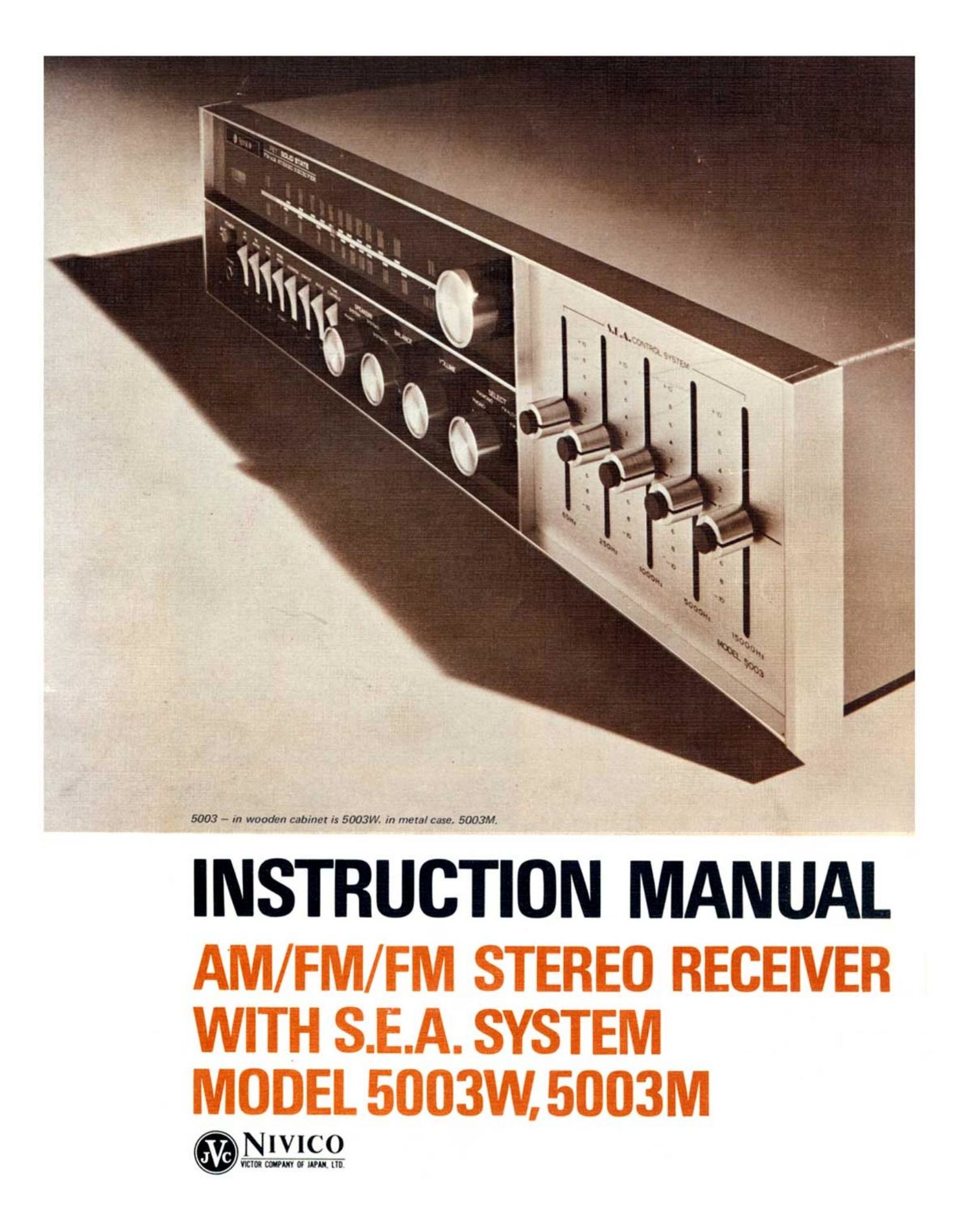
5003 - m wooden cabinet is 5003W. in metal case. 5003M.

INSTRUCTION MANUAL

NIVICO

YUM mm U NM ["1

Page 2

The set is designed to operate on
all AC line voltages and frequencies from 100 to 240V, 50
or 60Hz. Before plugging in the power cord, make sure that
the voltage indicated on the tag of the cord agrees with the
voltage requirements of your area.
To select voltages, loosen the four screws which hold the set
cover in position and remove the cover. If the case is
wooden, loosen the six screws on the bottom of the cabinet
and remove the cabinet by pulling it forward. Connect the
voltage selecting plug at the left corner of the chassis, after
making sure that the voltage indicated on the plug agrees
with the voltage of your AC power requirements, Fig. 1. 2.

w
2
<
l
l
5
o
<

uti- -1215

Limited inter-station noise may
sometimes be heard during FM reception. To correct this,
use the FM muting adjustor-(26) in Fig.6-located on the
back of the set. Connect either the feeder antenna

(supplied), or an outdoor antenna to the FM ANTENNA
termina|»(27l in Fig. 6. Tune to a position where the
maximum amount of noise can be heard. Then set the
muting switch-(11) in Fig. 5- to MUTING. Use a screw
driver to turn the FM muting adjustor, Fig. 3, until the
inter-station noise is reduced.

Fig.3

A highly sensitive bar antenna for
AM reception is located at the back of the set. In areas with
weak radio signals, proper reception depends on the
direction of this bar antenna. Before using the set, extend
the bar antenna outward, Fig. 4. When the set is being
carried, put the antenna back into position.

Fig. 4