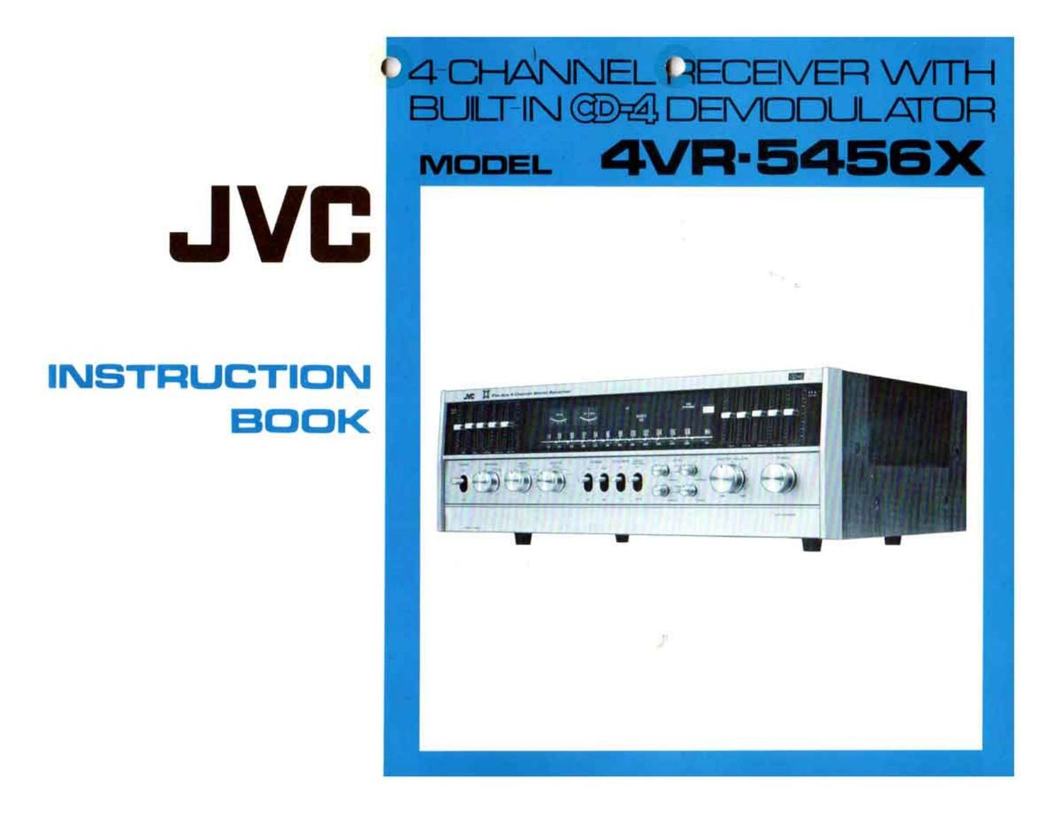
Jvc 4VR 5456X Owners Manual

This is the 22 pages manual for Jvc 4VR 5456X Owners Manual.
Read or download the pdf for free. If you want to contribute, please mail your pdfs to info@audioservicemanuals.com.

Page: 1 / 22
left right
Jvc 4VR 5456X Owners Manual

Extracted text from Jvc 4VR 5456X Owners Manual (Ocr-read)


Page 2

PRECAUTIONS

' Leave space round the receiver for ventilation.

' Do not connect equipment requiring more than the rated power to the AC
sockets on the rear panel.

Turn off the power before connecting any components as the click noise could
damage the speakers.

' Connect the speaker and input terminals correctly as wrong polarity or shorting
will result in unstable sound or the blowing of a fuse. A poor ground contact
may result in hum which may damage the speakers.

' Use speakers with the correct impedance. (See below)

' Take care with the AC plug. Do not bend the cord perpendicularly to the plug,
grasp the plug when pulling it from the AC outlet and don't apply any force
to the cord.

' CD-4 adjustment is to match the cartridge and stylus with the demodulator.
If this is not done CD-4 sound will deteriorate. (See page 8)

' If your receiver is too close to a TV receiver you may have interference problems
when playing CD4 records. Move the receiver 3 to 4 ft from the TV.

SPEAKERS

When you are playing 4-channel sound the speakers can be between 452 and 169.
When you are playing BTL double power 2-channel sound and when playing
4channel systems 1 + 2 the speakers should not be less than 80.

With the 4VR-5456X dachannel and double power BTL operations can be selected
by the front panel speaker switch. When speakers are connected with a common
negative ground with the Speaker switch in its OFF position sound may be heard
and when it is in its BTL positions abnormal effects may be heard. The speaker
switching boxes most commonly used use a common negative ground and so if you
are using a switching box only the 40H position should be used.

WARNING: TO PREVENT FIRE OR SHOCK HAZARD, DO NOT
EXPOSE THIS APPLIANCE TO RAIN OR MOISTURE.

CONTENTS

Connection diagram ........................................ 2
Rear panel .............................................. 3
Upper front panel ......................................... 4
Lower front panel ......................................... 6
Antenna connection ........................................ 7
Protectioncircuit............... .......................... 7
Fuse .................................................. 1
CD4 adjustment .................... . ..................... 8
Operation - Playing CD-4 records .............................. g

- Playing other records .............................. 9

- Receiving broadcasts .............................. 9

- Playing tapes ............. . ...................... 10

.- Recording and monitoring .......................... 10
S.E.A. recording .......................................... 10
Tape dubbing ............................................ 11
BTL - Double power 2-channel sound ........................... 12
Connection of Noise Reduction unit ............................. 12
FM 4-Channel ............................................ 12
S.E.A. ................................................ 13
4-Channel balance ......................................... 15
SCOPE OUT iacks ......................................... 15
Operation chart .......................................... 13
Performance waphs ........................................ 17
Troubleshooting .......................................... 18
Specifications ..... ' ...................................... 20

Page 8

ANTENNA CONNECTION

The 4VR-5456X has built-in AM and FM antennas. If you live in a weak signal area
you may find it necessary to fit external indoor or outdoor antennas for improved
reception.

The antennas should be fitted as shown in the diagram. The AM antenna should be
connected to the AM terminal and ground terminal. A 7552 FM antenna should be
connected to the 759 and ground terminals. A 3000 FM antenna should be con
nected to the 3009 FM antenna terminals.

If your record player has a ground cord this also should be connected to the ground
terminal.

The onetouch terminals provided ensure that you easily get the best electric contact
possible.

Strip about 1/2" at the end of the cord, press the terminal, insert the wire into the
hole in the terminal and release the terminal. The terminal now grips the wire giving
you perfect contact.

CAUTION : When you fit external antennas set the Antenna Switch to OFF.

FM ANTENNA CONNECTION

75H OUTDOOR ANTENNA 0R anon INDOOR ANTENNA

/- NTERNAL

I I


ON

OFF
WITCH TO OFF

FM Antenna

For good FM reception the best antenna possible must be provided. To get the
Optimum stereo reception it is necessary to eliminate reflected waves These cause
"ghosts" similar to those seen on TV. With a directional antenna it should be
oriented to reduce these reflections to a minimum. Tune to a broadcast and then
rotate the antenna till the signal strength meter makes its biggest deflection to the
riytt.

PROTECTION CIRCUIT

This receiver incorporates an automatic protection circuit recently developed by
JVC. (US. Pat. 3691427). It provides protection against current overloads for the
speakers and electronic components.

When the circuit operates sound will be intermittent. This is caused by relays
operating which disconnect the speakers from the output transistors in an overload
condition. Normal operation is automatically restored when loads drop below the
overload level. The first thing you must do when you hear intermittent sound is
check the speaker connections. Another cause of protection circuit operation could
be that you are operating the receiver at powers greater than it can safely handle;
in this case turn down the volume till the sound is no longer intermittent. This
condition is more likely to arise when you are playing 2-channel sound with the
BTL connection.

FUSE

If this fuse should ever fail it can be replaced by rotating the fuse holder counter-
clockwise and removing it. Always check the reason for any fuse blow-out before
making replacements. If something is wrong with the supply circuit the fuse will
blow again. In such a case consult a qualified electrician. In no case use copper wire
as a substitute for the specified fuse.

NOTE: Before replacing the fuse turn off the receiver and disconnect the power
supply cord from the AC outlet.

FUSE REPLACEMENT

Page 10

OPERATION

PLAYING CD-4 RECORDS

2 @9995.

Set the Mode selector to DISCRETE 46H.

Set the Source selector to CD4 I PHONO

Select one of the 4-channel positions with the Speaker selector.
Switch the power on.

Operate the record player according to its manufacturers instructions.
Adjust the Volume, Balance and Tone with the front panel controls.

OTES:

Before playing a CD-4 discrete 4-channel record for the first time, you should
adjust the C0-4 demodulator section of the receiver following the instructions
in "CD-4 Adjustment". (page 8)

To get the best possible CD-4 response keep your records and stylus clean. 00
not use cleaners which contain solvents and do not use water as this will increase
norse.

2-Channel records can be played back using the same playback equipment. The
service life of the records and stylus will not deteriorate in any way.

Set the phono sensitivity switch to HIGH.

To get the best CD-4 response use low caacitance signal cords between your
record player and receiver.

PLAYING OTHER. RECORDS

99PM.

Set the Mode selector to the required position.

MONO : Use this position when you want monaural sound.

2CH : Use this position when you want regular 2-channel stereo.

DISCRETE 4CH : If you use this position when you are not playing CD-4
records the MATRIX-I circuit will automatically be
switched in. This will decode matrix records and give
other records a achannel effect.

MATRIX-I Use this position when you want to play 80 records or
give 2-channel records a 4-channel effect.
MATRIX-2 Use this position when you want to play matrix records

other than 80 records.
Set the Source selector to CD4 PHONO.
Select the required position with the Speaker selector.
Switch the power on.
Operate the record player according to its manufacturers instructions.
Adjust the Volume, Balance and Tone with the front panel controls.

RECEIVING BROADCASTS

1.

99.

Set the Source selectOr to the required position.
AM : To receive AM broadcasts.
FM : To receive FM broadcasts.
Set the Mode selector to the required position.

MONO To get monaural sound from AM and FM broadcasts.

20H : To get com/entional stereo sound from FM stereo broad-
casts.

MATRIX-1 To reproduce FM stereo broadcasts which have been
encoded by the SO matrix system to give them a 4-channel
effect and to get a 4-channel effect from regular stereo
broadcasts.

MATRIX-2 To reproduce FM broadcasts which have been given a

4-channel effect by encoding by any other matrix system

than 50.
Set the Speaker selector to the desired position.
Switch the power on.
With the Volume control set at a low level, turn the Tuning knob slowly to
tune into the required station.
When you tune to an FM Stereo broadcast FM STEREO is displayed on the
front panel.
When you are tuning the signal strength meter makes its biggest swing to the
right when you are tuned accurately. When you tune to an FM broadcast
the center tuning meter will be in its central position.
When you are correctly tuned to the station you require. adjust the Volume,
Balance and Tone with the front panel controls.
When noise reduction processed FM broadcasts start, connect an external
Noise Reduction unit to the rear panel TAPE-1 jacks and put the TAPE MON/
EXT NR switch 1 down. (See page 12)
Switch on the FM Muting switch to eliminate interstation noise when tuning.
When tuned, switch it off.
Switch on the FM Stereo Only switch when you want to hear only FM stereo
broadcasts